An injection molding robot
A technology of manipulators and manipulators, which is applied in the field of injection molding manipulators, can solve the problems of easily damaged injection molded parts, scrapped injection molded parts, and easy adhesion of edge materials, etc., to achieve the effects of reducing accidental injuries, facilitating grasping, and reducing shedding
- Summary
- Abstract
- Description
- Claims
- Application Information
AI Technical Summary
Problems solved by technology
Method used
Image

Examples
Embodiment 1
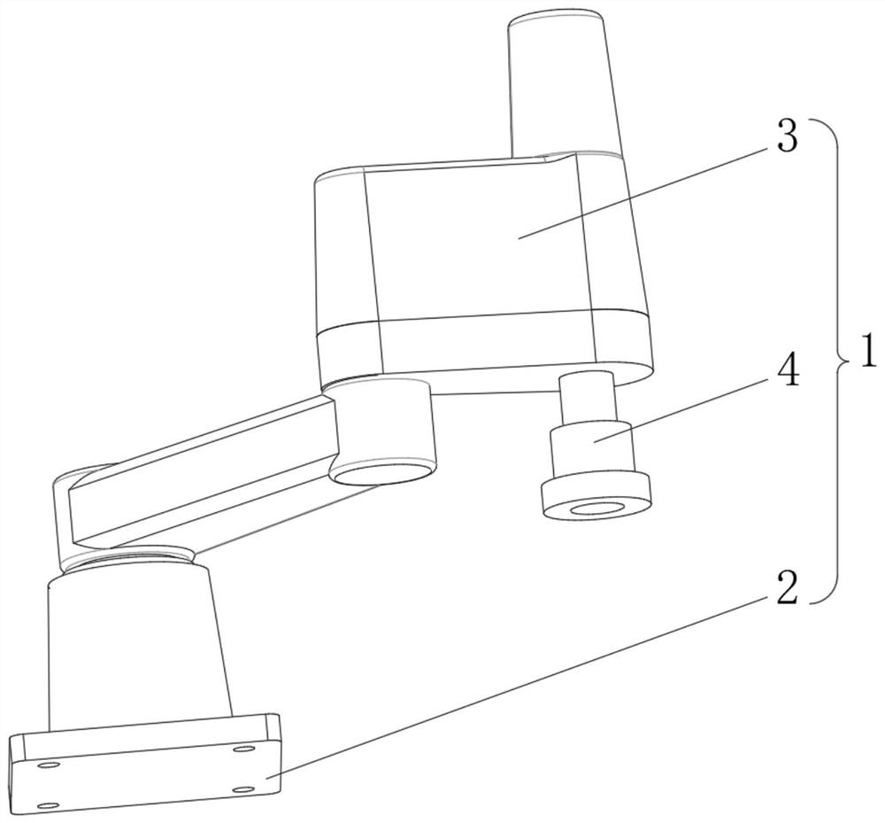
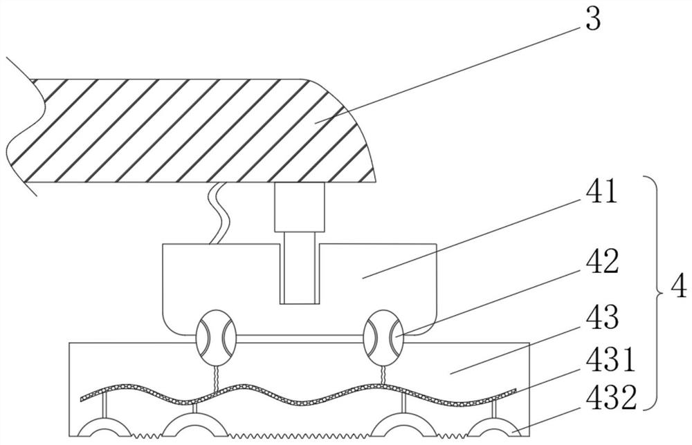
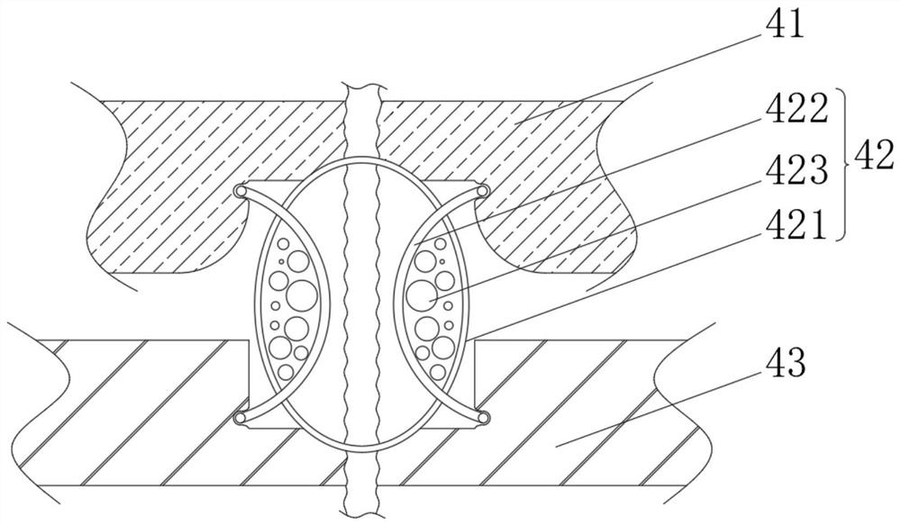
[0038] see Figure 1-3 , the present invention provides a technical solution: an injection molding manipulator, comprising an injection molding manipulator body 1 composed of a base 2, a manipulator 3 and a grasping mechanism 4, the top of the base 2 is fixedly connected to the bottom of the manipulator 3, and the bottom of the manipulator 3 The right side of the bottom is fixedly connected with the top of the grabbing mechanism 4. The grabbing mechanism 4 includes an upper bearing block 41, the inside of the upper bearing block 41 is slidingly connected with the bottom of the mechanical arm 3 through a hydraulic telescopic rod, and the bottom of the upper bearing block 41 is connected by a vibration block. 42 is fixedly connected with a lower bearing block 43, the inside of the lower bearing block 43 is provided with an air guide tube 431, the top of the air guide tube 431 communicates with the inside of the upper bearing block 41 through an air delivery pipe, and the inside o...
Embodiment 2
[0043] see Figure 1-5 , on the basis of Embodiment 1, the present invention provides a technical solution: the vibrating ring 422 includes a telescopic frame 4221, and a vibrating mechanism 5 is arranged inside the telescopic frame 4221, and an internal connecting rod 4222 is slidably connected to the internal part of the vibrating mechanism 5. A protective bag 4223 is fixedly connected to the outer side of the post 4222 , and the bottom of the protective bag 4223 is fixedly connected to the top of the vibrating mechanism 5 .
[0044] An elastic rod 4224 is fixedly connected to the outside of the inner connecting rod 4222 , and one end of the elastic rod 4224 away from the inner connecting rod 4222 is fixedly connected to the inside of the telescopic frame 4221 .
[0045] An electromagnetic block 4225 is fixedly connected to the bottom of the elastic rod 4224, and the inside of the electromagnetic block 4225 is electrically connected to an external AC power supply through wir...
Embodiment 3
[0050] see Figure 1-6 , on the basis of Embodiment 1 and Embodiment 2, the present invention provides a technical solution: the impact mechanism 53 includes an impact frame 531, a spring 532 is arranged inside the impact frame 531, and the top and bottom ends of the spring 532 are fixedly connected with Piston plate 533, the outer side of piston plate 533 is slidingly connected with the inner wall of impact frame 531, and one end of piston plate 533 away from spring 532 is fixedly connected with impact ball 534 through elastic strip, and the inner wall of impact frame 531 is fixedly connected with anti-collision block 535.
[0051] During use, when the electromagnetic blocks 4225 interact with each other, the electromagnetic blocks 4225 squeeze the pressure capsule 51 mutually, and the inside of the pressure capsule 51 is connected to the inside of the impact frame 531 through a pressure tube, and the piston plate 533 in the impact mechanism 53 is subjected to The air is sque...
PUM
 Abstract
Description
Claims
Application Information
 - R&D
- Intellectual Property
- Life Sciences
- Materials
- Tech Scout
- Unparalleled Data Quality
- Higher Quality Content
- 60% Fewer Hallucinations
Browse by: Latest US Patents, China's latest patents, Technical Efficacy Thesaurus, Application Domain, Technology Topic, Popular Technical Reports.
© 2025 PatSnap. All rights reserved.Legal|Privacy policy|Modern Slavery Act Transparency Statement|Sitemap|About US| Contact US: help@patsnap.com