Clamping device for laser cutting machine

A laser cutting machine and clamping device technology, applied in laser welding equipment, welding equipment, metal processing equipment, etc., can solve problems such as unreasonable use of time, reduced processing speed and efficiency, cumbersome operation, etc., to prevent harm to operators The effect of health, reduction of unqualified rate, and rational use of time

Inactive Publication Date: 2021-06-04
张荷友
View PDF5 Cites 0 Cited by
  • Summary
  • Abstract
  • Description
  • Claims
  • Application Information

AI Technical Summary

Problems solved by technology

With the movement of the relative position of the beam and the workpiece, the material will eventually form a slit, so as to achieve the purpose of cutting. The laser cutting process uses an invisible beam instead of the traditional mechanical knife. It has high precision, fast cutting, and is not limited to cutting. Pattern limitation, automatic typesetting saves material, smooth cut, low processing cost, etc., will gradually improve or replace traditional metal cutting process equipment; the current clamping device for cutting machine requires manual clamping of the workpiece, and can only Clamp the plate of the same size, the clamping range is small, after the processing is completed, the control machine stops, and then the workpiece is disassembled, the unprocessed workpiece is installed and fixed, and finally restarted, the operation is cumbersome, the time cannot be used reasonably, and the processing time is delayed. Processing speed and efficiency; on the other hand, the workpiece will be dirty during transportation, and the laser cutting machine has different penetration power to metal and non-metal, and the dirt on the workpiece plate will affect the processing. If manual cleaning is used, it will increase Processing cost; At the same time, during laser cutting, harmful gas will be produced, if not handled in time, it will cause harm to the health of operators; not safe enough; in order to solve the above problems, a clamping device for laser cutting machine is proposed in this application

Method used


Image

  • Clamping device for laser cutting machine
  • Clamping device for laser cutting machine
  • Clamping device for laser cutting machine

Examples


Embodiment Construction

[0029] In order to make the objectives, technical solutions and advantages of the present invention clearer, the present invention will be further described in detail below with reference to the specific embodiments and the accompanying drawings. It should be understood that these descriptions are exemplary only and are not intended to limit the scope of the invention. Also, in the following description, descriptions of well-known structures and techniques are omitted to avoid unnecessarily obscuring the concepts of the present invention.

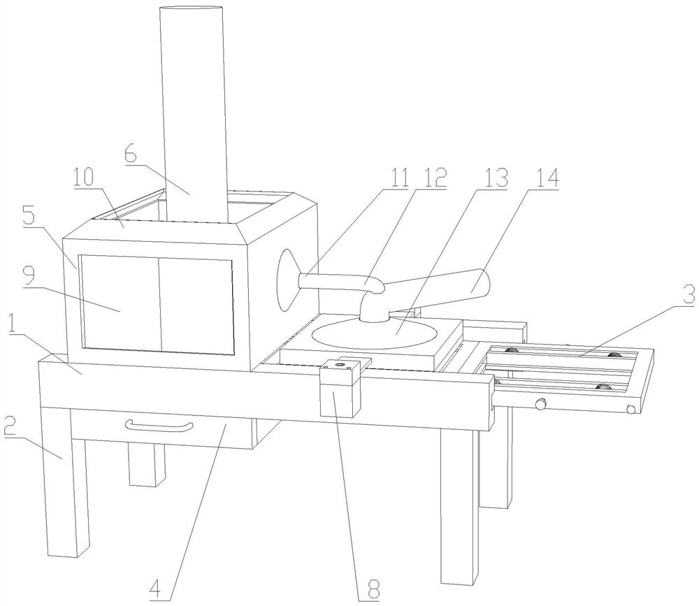
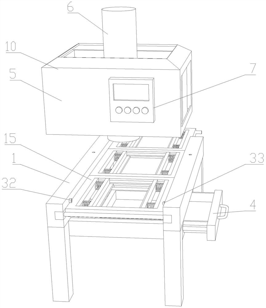
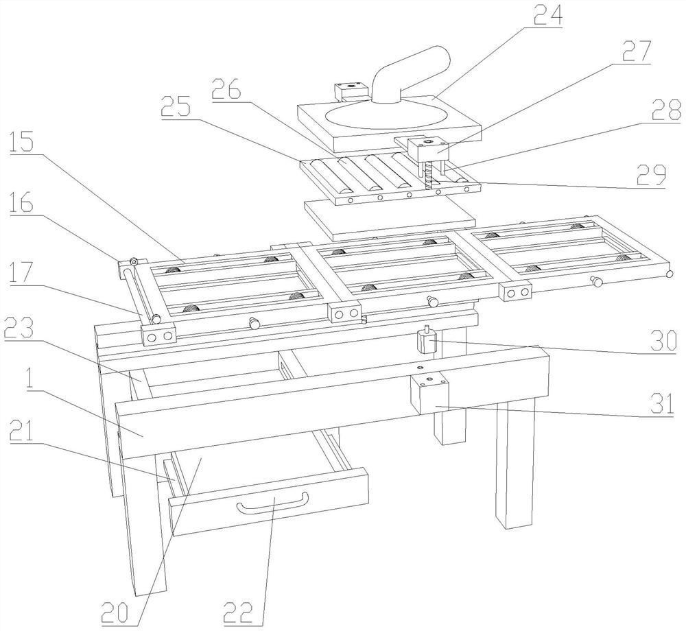
[0030] like Figure 1-5 As shown, a clamping device for a laser cutting machine proposed by the present invention includes a guide rail 1, a supporting foot 2, a transport device 3, a storage device 4, a cutting box 5, a cutting machine 6, an adjustment component 8, and a smoke shield 10. , smoking pipe 11, first trachea 12, receiver 32 and transmitter 33;

[0031] The guide rail 1 is set on the worktable through the supporting feet 2, an...


PUM


Abstract

The invention discloses a clamping device for a laser cutting machine. The clamping device comprises a guide rail, a conveying device, a storage device, a cutting box, an adjusting assembly and a smoke suction hopper. The cutting box is arranged on the guide rail, and the smoke suction hopper is arranged on the cutting box. A fixing box is arranged on the guide rail and located below an object carrying piece, and a sliding strip is arranged on a drawer box and is in sliding connection with the fixing box. A fixing block is arranged on the guide rail, a movable piece is arranged on a dust collecting cover, a guide column is arranged on the movable piece and is in sliding connection with the fixing block, and a threaded rod is arranged on a rotating shaft on a motor and is in threaded connection with the movable piece. A cleaning roller is arranged on a fixing plate. A receiver is arranged on the guide rail and is in communication connection with a controller, and an emitter is arranged on the guide rail and located on the opposite side of the receiver. According to the clamping device, automatic feeding can be achieved, time is reasonably utilized, the machining efficiency is improved, different workpieces can be clamped and cleaned, dirt is prevented from influencing cutting machining, the reject ratio is reduced, harmful gas generated by cutting can be cleared away and exhausted, and safety is higher.

Description

technical field [0001] The invention relates to the technical field of cutting equipment, in particular to a clamping device for a laser cutting machine. Background technique [0002] Laser cutting is to focus the laser emitted from the laser into a high power density laser beam through the optical path system. The laser beam is irradiated on the surface of the workpiece, making the workpiece reach the melting point or boiling point, while the high-pressure gas coaxial with the beam blows the molten or vaporized metal away. With the movement of the relative position of the beam and the workpiece, the material is finally formed into a slit, so as to achieve the purpose of cutting. The laser cutting process replaces the traditional mechanical knife with an invisible beam, with high precision and fast cutting, not limited to cutting Pattern restrictions, automatic typesetting to save materials, smooth incisions, and low processing costs will gradually improve or replace tradit...

Claims


Application Information

Patent Timeline
Patent Type & Authority Applications(China)
IPC IPC(8): B23K26/38B23K26/70
CPCB23K26/38B23K26/702
Inventor 张荷友
Owner 张荷友
Why Eureka
Try Eureka