
Implementation method of high-gain omnidirectional biconical antenna array

A technology of biconical antenna and implementation method, which is applied in the direction of manufacturing antenna array devices, antenna arrays, antennas, etc., and can solve problems such as deterioration of out-of-roundness, affecting the practical application of antennas, and affecting the omnidirectionality of the azimuth plane pattern

Active Publication Date: 2021-06-01
THE 724TH RES INST OF CHINA SHIPBUILDING IND
View PDF4 Cites 1 Cited by
  • Summary
  • Abstract
  • Description
  • Claims
  • Application Information

AI Technical Summary

Problems solved by technology

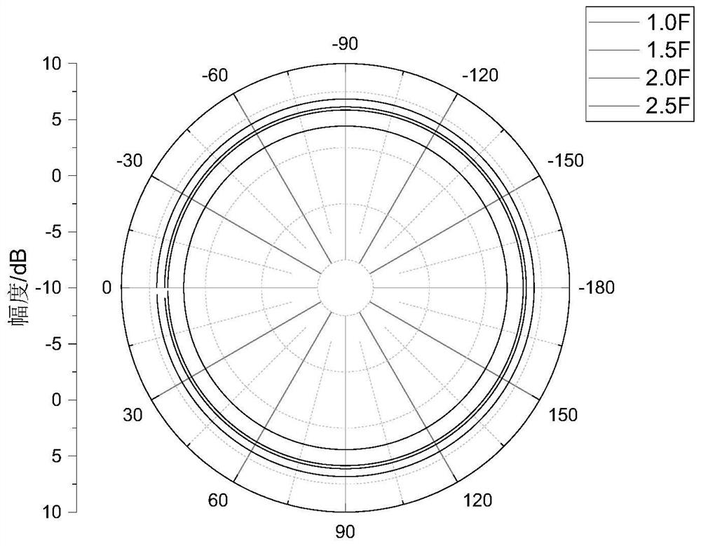
[0003] The existing high-gain omnidirectional antennas are implemented in the following ways: multiple high-gain wide-coverage antennas are used to synthesize omnidirectional antennas in the azimuth plane, and multiple omnidirectional antenna units are arrayed in series or parallel feed , a typical high-gain series-fed omnidirectional antenna such as "COCO" antenna, its elevation beam pointing will change with frequency within the bandwidth; while using conventional parallel feed, the amplitude and phase of each unit are independently controllable, and the elevation beam The shape can be configured arbitrarily, but when the feeder passes near the antenna, it will have a significant impact on the antenna pattern: when the feeder passes near the omnidirectional antenna, it will greatly affect the omnidirectionality of the azimuth pattern, and its out-of-roundness will deteriorate by up to More than 3dB, which seriously affects the practical application of the antenna

Method used


Image

  • Implementation method of high-gain omnidirectional biconical antenna array
  • Implementation method of high-gain omnidirectional biconical antenna array
  • Implementation method of high-gain omnidirectional biconical antenna array

Examples


Embodiment

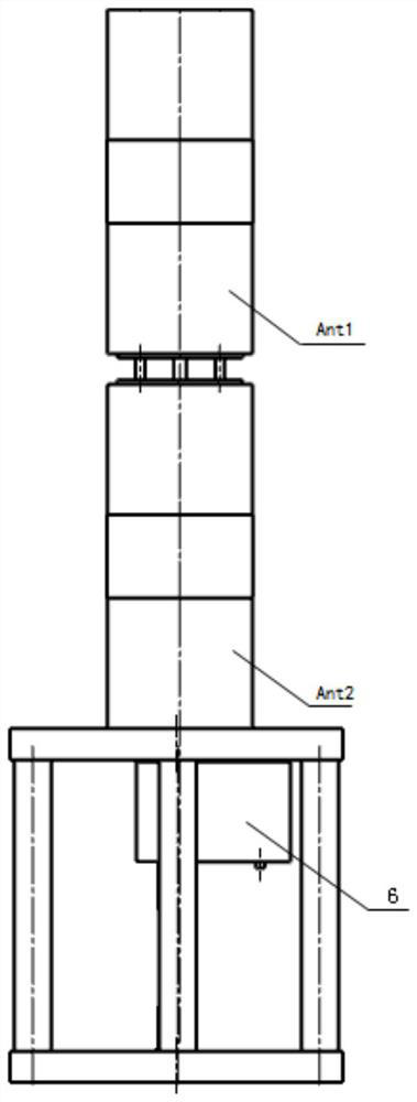
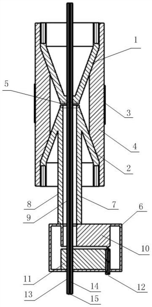
[0019] Embodiment: The two-unit high-gain omnidirectional biconical antenna array designed by the method of the present invention is as attached figure 1 As shown, the main steps are as follows:

[0020] 1. Design the antenna unit according to the bandwidth: the design of the biconical antenna unit belongs to the public technology and will not be described again. The height H2 and the radius of the cylindrical step at the top of the cylindrically loaded biconical antenna cone are adjusted according to the VSWR in the band; the upper cone 1 and lower cone 2. The top diameters are Φ1 and Φ2. The size of the through hole is determined according to the size of the feed coaxial line used for the position of the unit in the array.

[0021] 2. Nested feed coaxial cable design: Nested coaxial cable means that the feed coaxial cable of the upper unit passes through the fed coaxial cable of the lower unit, and its outer conductor serves as the fed coaxial cable of the lower unit The i...


PUM


Abstract

The invention relates to an implementation method of a high-gain omnidirectional biconical antenna array. The implementation method is mainly used for improving the omnidirectional degree of an omnidirectional antenna in a broadband range and acquiring a pitching wave beam with good in-band consistency at the same time. The high-gain omnidirectional biconical antenna array is composed of a plurality of cylindrical loading special-shaped sleeve biconical antenna units arrayed by pitching surfaces and an array feeder, wherein the top of a cone of each sleeve biconical antenna unit is provided with a cylindrical load so as to improve an in-band voltage standing wave ratio; each array unit is directly excited through a coaxial line, an inner conductor of the coaxial line is connected with an upper half cone of the unit, and an outer conductor is connected with a lower half cone; one upper biconical antenna feed coaxial line passes through the inner conductor of one lower unit feed coaxial line in sequence to form a nested coaxial line, and feed structures do not interfere with each other; and the nested coaxial line is converted into an independent feed connector through a coaxial ridge waveguide conversion pair below the coaxial line. The method is suitable for design and implementation of the high-gain omnidirectional biconical antenna array.

Description

technical field [0001] The invention belongs to the technical direction of communication, radar antenna and microwave. Background technique [0002] In general, the antenna is required to have a large antenna gain in the desired specific angular direction, while other undesired directions have low sidelobes or even no ability to radiate. As a special type of antenna, the omnidirectional antenna requires omnidirectional beam coverage in the azimuth plane, and at the same time has a constant beam pointing or specific coverage in the band on the elevation plane, which is often impossible to achieve with a single antenna, which requires the use of The design idea of ​​the antenna array is to reasonably configure the amplitude and phase of each omnidirectional antenna unit to maintain the azimuth and omnidirectional while improving the antenna gain and achieving specific elevation coverage. [0003] The existing high-gain omnidirectional antennas are implemented in the following...

Claims


Application Information

Patent Timeline
IPC IPC(8): H01Q21/00
CPCH01Q21/0087H01Q21/0006
Inventor 肖鸿杨康申强强汪隽潇
Owner THE 724TH RES INST OF CHINA SHIPBUILDING IND
Learn More