Wide-angle lens and imaging equipment
A technology of wide-angle lens and imaging surface, which is applied in the field of imaging lens to achieve good thermal stability, eliminate ghost, and shorten the effect of back focus
- Summary
- Abstract
- Description
- Claims
- Application Information
AI Technical Summary
Problems solved by technology
Method used
Image

Examples
no. 1 example
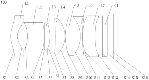
[0066] see figure 1 , which is a schematic structural view of the wide-angle lens 100 provided in the first embodiment of the present invention, the wide-angle lens 100 includes in sequence from the object side to the imaging surface along the optical axis: a first lens L1, a second lens L2, a third lens L3, and a diaphragm ST, fourth lens L4, fifth lens L5, sixth lens L6, seventh lens L7, and filter G1.
[0067] The first lens L1 has negative refractive power, the object side S1 of the first lens is a convex surface, and the image side S2 of the first lens is a concave surface.
[0068] The second lens L2 has negative refractive power, the object side S3 of the second lens is concave, and the image side S4 of the second lens is convex.
[0069] The third lens L3 has positive refractive power, the object side S5 of the third lens is concave, and the image side S6 of the third lens is convex.
[0070] The fourth lens L4 has positive refractive power, the object side S7 of the...
no. 2 example
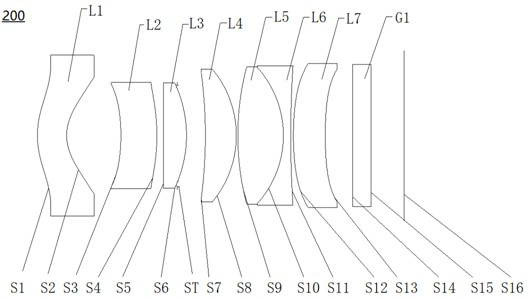
[0083] see image 3 , shows a structural diagram of the wide-angle lens 200 provided by the second embodiment. The wide-angle lens 200 among the present embodiment is roughly the same as the wide-angle lens 100 among the first embodiment, the difference is that the second lens L2 of the wide-angle lens 200 among the present embodiment has positive refractive power, and the object side surface S5 of the third lens L3 is The plane (the plane can be regarded as a spherical surface with an infinite radius of curvature), and the radius of curvature of each lens, the distance between the lenses and the selection of materials are different; among them, setting the object side S5 of the third lens as a plane can make the tolerance of the system better, And the plane is easy to process, the yield rate is high, and the production is convenient.
[0084] Table 3 shows relevant parameters of each lens of the wide-angle lens 200 provided in this embodiment.
[0085] table 3
[0086] ...
no. 3 example
[0092] see Figure 5 , shows the structure diagram of the wide-angle lens 300 provided by the third embodiment. The wide-angle lens 300 among the present embodiment is roughly the same as the wide-angle lens 100 among the first embodiment, the difference is that the second lens L2 of the wide-angle lens 300 among the present embodiment has positive refractive power, and the object side surface S5 of the third lens L3 is The convex surface, the object side S9 of the fifth lens L5 is a plane, the image side S11 of the sixth lens L6 is a plane, and the radius of curvature, distance between lenses and material selection of each lens are different. The setting of the plane greatly reduces the processing cost of the lens, and effectively improves the tolerance of the system, and the processability is better.
[0093] The relevant parameters of each lens of the wide-angle lens 300 provided in this embodiment are shown in Table 5.
[0094] table 5
[0095]
[0096] The relevant ...
PUM
 Abstract
Description
Claims
Application Information
 - R&D
- Intellectual Property
- Life Sciences
- Materials
- Tech Scout
- Unparalleled Data Quality
- Higher Quality Content
- 60% Fewer Hallucinations
Browse by: Latest US Patents, China's latest patents, Technical Efficacy Thesaurus, Application Domain, Technology Topic, Popular Technical Reports.
© 2025 PatSnap. All rights reserved.Legal|Privacy policy|Modern Slavery Act Transparency Statement|Sitemap|About US| Contact US: help@patsnap.com