Solar inflatable temperature control heat pipe device

A solar and warm technology, applied in the direction of solar thermal energy, solar thermal power generation, solar thermal collectors, etc., can solve the problems of solar heat source fluctuations, increased heat exchange costs, and low efficiency

Pending Publication Date: 2021-06-01
NANCHANG UNIV
View PDF0 Cites 2 Cited by
  • Summary
  • Abstract
  • Description
  • Claims
  • Application Information

AI Technical Summary

Problems solved by technology

However, the heat source of solar energy fluctuates violently. For example, in the recycling of solar energy, because the solar energy fluctuates violently with the weather and time, there is often a situation where the recovered heat does not match the user load.
The general heat treatment method is to use peripheral control equipment to regulate, but this will increase the cost of heat exchange invisibly, and the efficiency is low

Method used


Image

  • Solar inflatable temperature control heat pipe device
  • Solar inflatable temperature control heat pipe device

Examples


Embodiment Construction

[0019] Below in conjunction with accompanying drawing and embodiment the present invention will be further described:

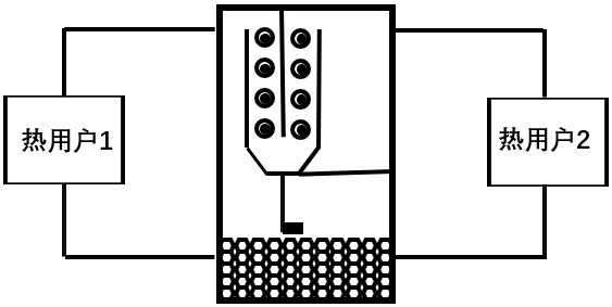
[0020] see Figure 1-2 .

[0021] The basic structure of temperature control heat pipe 1 is shown in figure 1 , Its basic structure includes evaporating section 2, condensing section 3 and air storage chamber 4 three parts. The evaporating section 2 is water as the heat transfer medium of the heat pipe, and the condensing section 3 is provided with two parts, the first condensing section 301 and the second condensing section 302, which respectively contain drain pipes 5, wherein the first condensing section 301 leads to the heat user 1, and the second condensing section 302 The second condensation section 302 leads to the heat user 2 . After the inside of the heat pipe is pumped into a vacuum state, a certain amount of non-condensable gas is filled into the gas storage chamber. The non-condensable gas can be R22, N 2 When the heating power of the evaporat...


PUM


Abstract

The invention discloses a heat treatment device with a temperature control heat pipe. The device comprises the temperature control heat pipe, wherein the temperature control heat pipe is formed by an evaporation section, a condensation section and a gas storage chamber; the evaporation section is arranged at the bottom of an inner cavity of the temperature control heat pipe; the condensation section is arranged in the middle of the inner cavity of the temperature control heat pipe; the condensation section is provided with a drainage pipe for heat exchange; a condensate return pipe is arranged at the bottom of the condensation section; the gas storage chamber is arranged at the top of the inner cavity of the temperature control heat pipe; a baffle at one side of the gas storage chamber divides the condensation section into a first condensation section and a second condensation section; the first condensation section is arranged at the side, close to the condensation section, of the evaporation section; and the second condensation section is arranged on the side, close to the condensation section, of the gas storage chamber. According to the device, the space occupied by the non-condensable gas is influenced by changing the heating power, so that more row pipes participate in heat exchange, the temperature of a working medium of the heat pipe is basically kept unchanged, and the effects of temperature control and heat management are achieved.

Description

technical field [0001] The invention relates to the field of solar heat recovery, in particular to a heat treatment device with a temperature-controlling heat pipe. Background technique [0002] Heat pipe is an efficient heat transfer element, which has the advantages of high heat transfer efficiency, uniform temperature, simple structure, reliable operation, etc., and is widely used in various occasions. At present, temperature-controlled heat pipes with the property of maintaining working temperature have been widely used in the aerospace field. [0003] Solar energy is strongly advocated as a pollution-free clean energy. Solar heat recovery is a way to absorb solar radiation energy and transfer heat to working fluid. With the improvement of the living standard of human society, the solar heat recovery method is more and more widely used in daily life and industry because of its environmental protection and high efficiency. However, the heat source of solar energy fluct...

Claims


Application Information

Patent Timeline
Patent Type & Authority Applications(China)
IPC IPC(8): F24S10/95F24S50/40
CPCF24S10/95F24S50/40Y02E10/44
Inventor 张莹赵启晨徐猛徐勋
Owner NANCHANG UNIV
Why Eureka
Try Eureka