
Tool manufacturing method for preventing air leakage of composite material forming tool

A composite material and forming tooling technology, which is applied in the field of tooling manufacturing to prevent composite material forming tooling from leaking, can solve problems affecting the use of forming tooling, tooling splitting or air leakage, and affecting tooling airtightness, etc., to reduce maintenance costs , to ensure the internal quality, to ensure the effect of high temperature air tightness

Active Publication Date: 2021-06-01
航天海鹰(镇江)特种材料有限公司
View PDF6 Cites 0 Cited by
  • Summary
  • Abstract
  • Description
  • Claims
  • Application Information

AI Technical Summary

Problems solved by technology

However, due to the lack of fiber support at the joints of lap joints or butt joints, especially the joints where thick tooling prepregs are joined, tooling splits or air leakage are prone to occur, which in turn affects the airtightness of the tooling
[0008] In addition, the process margin needs to be considered in the manufacturing process of traditional composite molding tooling. Generally, the whole layer is paved from the edge of the tooling when paving. After the demoulding process is completed, the tooling is manually trimmed or CNC milled. The edge is trimmed; due to the fixed fiber direction of the paving tooling prepreg, once the edge of the tooling is trimmed or the edge of the tooling is bumped and worn, it is very easy to produce fine cracks, and these cracks will extend along the fiber direction To the net size area of ​​the tooling, penetrating cracks will occur, which will cause air leakage of the tooling and affect the use of the entire forming tooling

Method used


Image

  • Tool manufacturing method for preventing air leakage of composite material forming tool
  • Tool manufacturing method for preventing air leakage of composite material forming tool
  • Tool manufacturing method for preventing air leakage of composite material forming tool

Examples


Embodiment Construction

[0042] The technical scheme of the present invention will be clearly and completely described below in conjunction with the embodiments and the accompanying drawings. Obviously, the described embodiments are only preferred embodiments of the present invention, not all embodiments, nor are they intended to be a reference to the present invention. For other forms of limitations, any skilled person who is familiar with this field may use the disclosed technical content to make changes or remodel equivalent changes. However, any simple modifications, equivalent changes and modifications made to the above embodiments according to the technical essence of the present invention without departing from the content of the technical solution of the present invention still belong to the protection scope of the technical solution of the present invention.

[0043] This embodiment is to manufacture a composite material forming tool for forming a certain type of composite material part. The ...


PUM

PropertyMeasurementUnit
Widthaaaaaaaaaa

Abstract

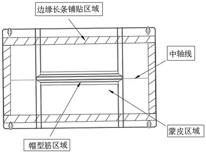
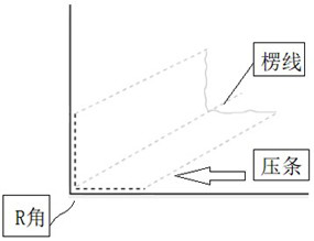
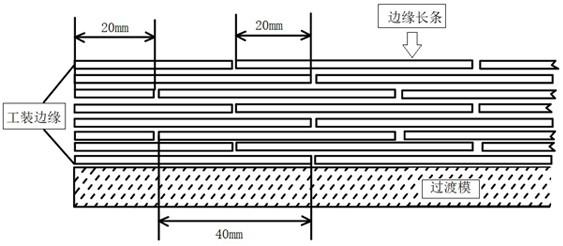
The invention discloses a tool manufacturing method for preventing air leakage of a composite material forming tool. The composite material forming tool is used for forming a composite material part. The composite material forming tool is formed by assembling a composite material paving die and a supporting frame. The composite material paving die is formed by paving and hot-pressing tool prepreg with different thicknesses on the basis of a transition die. In the paving process, pressing strips are paved in the R area and the corner area of the transition die, the tool prepreg is paved in the edge allowance area of the tool in a photo frame mode, and a seam filling long strip is paved in the butt joint area. The photo frame type paving avoids expansion of the edge defect caused by cutting to the interior and cracking during collision or demolding in the carrying process; and the high-temperature air tightness of the tool is further ensured by the pressing strips and the seam filling long strip. The tool manufactured by the method is good in air tightness, the maintenance cost is effectively reduced, the forming quality and the manufacturing period of the composite material part are guaranteed, and good practical and economic values are achieved.

Description

technical field [0001] The invention relates to a tooling manufacturing method for preventing composite material forming tooling from air leakage. Background technique [0002] Composite parts (hereinafter referred to as composite parts) are made of resin-based carbon fiber composite materials. Due to the advantages of resin-based carbon fiber composite materials, such as high specific strength and specific stiffness, high degree of structural integration, strong designability, good fatigue resistance, corrosion resistance, and good dimensional stability, it has become a popular choice for aviation, aerospace, transportation, etc. High-performance structural materials widely used in the field. Since the manufacture of composite parts must use specially designed tooling to complete the compounding of materials and the forming process of parts at the same time. Composite parts hardly need any further processing after solidification and molding, and their internal structure a...

Claims


Application Information

Patent Timeline
IPC IPC(8): B29C70/34B29C70/54
CPCB29C70/342B29C70/54B29C70/545
Inventor 孙龙港王滢郭渊谢海洋马秀菊黎玉钦孙成姚海涛
Owner 航天海鹰(镇江)特种材料有限公司
Learn More