Electromagnetic ball valve with positioning function

A technology of electromagnetic ball valves and ball valves, which is applied in the direction of valve details, valve devices, and cocks including cut-off devices, etc., which can solve the problems of small use range of electromagnetic ball valves, short service life of electromagnetic ball valves, lack of electromagnetic ball valves, etc., and achieve flexible and convenient rotation , prolong service life, simple structure

Inactive Publication Date: 2021-05-28
程剑侠
View PDF8 Cites 2 Cited by
  • Summary
  • Abstract
  • Description
  • Claims
  • Application Information

AI Technical Summary

Problems solved by technology

[0004] The purpose of the present invention is to solve the existing electromagnetic ball valve. When in use, the temporal part of the electromagnetic cavity is usually electromagnetically energized through the coil, the stability is not high, and the positioning effect is poor, and there is no simple and fast operation of the electromagnetic ball valve. It is easy to cause the electromagnetic ball valve to be interfered by the coil, resulting in a short service life, and there is no mechanism for manual intervention on the electromagnetic ball valve in emergency situations such as power failure, resulting in a small range of use of the electromagnetic ball valve and poor stability, which cannot meet emergency situations. The shortcomings of the use, and a proposed electromagnetic ball valve with positioning

Method used


Image

  • Electromagnetic ball valve with positioning function
  • Electromagnetic ball valve with positioning function
  • Electromagnetic ball valve with positioning function

Examples


Embodiment Construction

[0038] The following will clearly and completely describe the technical solutions in the embodiments of the present invention with reference to the accompanying drawings in the embodiments of the present invention. Obviously, the described embodiments are only some, not all, embodiments of the present invention. Based on the embodiments of the present invention, all other embodiments obtained by persons of ordinary skill in the art without creative efforts fall within the protection scope of the present invention.

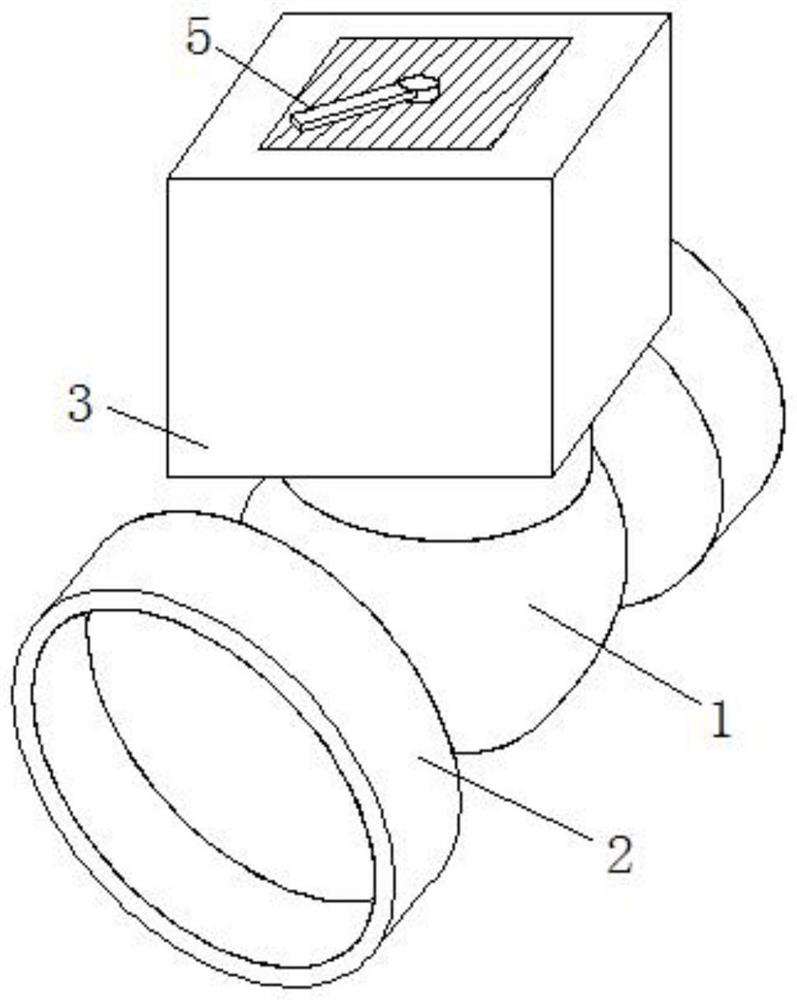
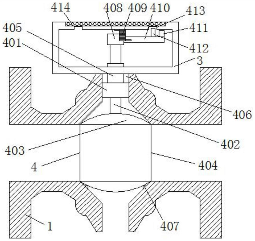
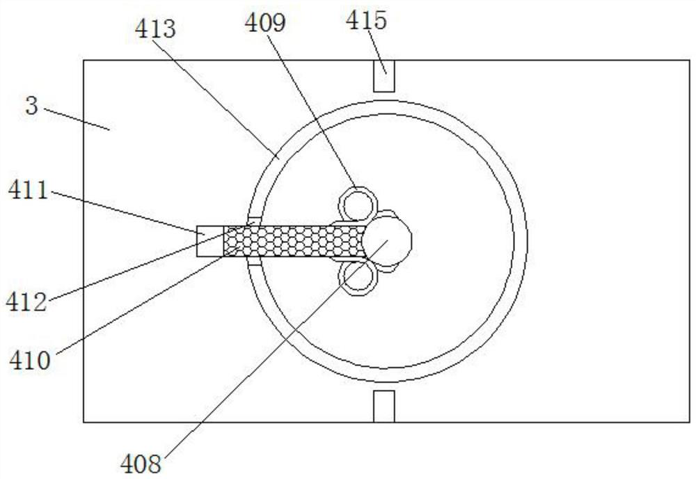
[0039] refer to Figure 1-5, a processing set-top box with a positioning electromagnetic ball valve, comprising a ball valve body 1, a connecting pipe 2, an electromagnetic cavity 3, a positioning mechanism 4, a fixed shaft 401, a ball valve stem 402, a ball 403, a through groove 404, a positioning shaft 405, Stem packing 406, valve seat 407, fixed top block 408, first torsion spring 409, rotating rod 410, fixed magnetic block 411, first slider 412, first chute 413...


PUM


Abstract

The invention discloses an electromagnetic ball valve with a positioning function. The electromagnetic ball valve comprises a ball valve body, wherein a connecting pipe is fixedly arranged on the outer side of the ball valve body, and an electromagnetic cavity is connected to the top of the ball valve body; and a positioning mechanism is arranged inside the ball valve body, and a fixing shaft is arranged inside the positioning mechanism. According to the electromagnetic ball valve with the positioning function, under the action of the positioning mechanism, an electromagnetic block is electrified to release magnetism, a fixed magnetic block is attracted by magnetism to move towards the electromagnetic block, and therefore a rotating rod slides inside the electromagnetic cavity through a first sliding block and a first sliding groove; under the action of a fixed top block, the rotating rod drives a ball valve rod to rotate; and therefore a ball can adjust internal circulation amount of the ball valve body through a through groove; and by means of the arrangement, a user can control the internal circulation amount of the ball valve through the electromagnetic block, and the situation that a coil is arranged inside the electromagnetic cavity is avoided; and the structure is simple, operation is convenient, later maintenance and service is convenient, and the service life of the electromagnetic ball valve is prolonged.

Description

technical field [0001] The invention relates to the technical field of electromagnetic ball valves, in particular to an electromagnetic ball valve with positioning. Background technique [0002] The control valve is one of the main components of the hydraulic system. The electromagnetic ball valve is a kind of control valve. The electromagnetic ball valve is an electromagnetic control valve with a spherical valve core. In addition to all the characteristics of the electromagnetic valve, it also has its unique Some characteristics, it uses the thrust of the electromagnet as the driving force to push the steel ball to realize the oil circuit on-off ball type electromagnetic reversing valve, which is suitable for the hydraulic system with various mineral oils as the working medium, so as to realize the pilot control without leakage , when meeting the requirements of the flow-pressure drop characteristic, it can also be used as the direction control of other actuators. [0003]...

Claims


Application Information

Patent Timeline
Patent Type & Authority Applications(China)
IPC IPC(8): F16K5/06F16K5/08F16K5/12F16K31/06F16K31/08F16K37/00F15B13/02
CPCF16K5/0647F16K5/08F16K5/12F16K37/0008F16K37/0058F16K31/0644F16K31/082F15B13/02
Inventor 程剑侠
Owner 程剑侠
Why Eureka
Try Eureka