
Detachable floor system connecting joint for modular steel structure and manufacturing method thereof

A technology for connecting nodes and steel structures, applied in the direction of floors, building components, building structures, etc., can solve problems such as insufficient plane stiffness and discontinuity, and achieve the effect of enhancing robustness, facilitating repair, and facilitating disassembly.

Pending Publication Date: 2021-05-28
CIMC MODULAR BUILDING SYST HLDG CO LTD +2
View PDF0 Cites 0 Cited by
  • Summary
  • Abstract
  • Description
  • Claims
  • Application Information

AI Technical Summary

Problems solved by technology

[0005] The present invention aims to overcome the problems of in-plane discontinuity and in-plane rigidity of existing modular steel structure floors, and provide a detachable floor connection node and its construction for modular steel structures with convenient construction and high load-bearing performance. method, under the premise of giving full play to the advantages of modular building assembly, strengthen the horizontal connection between modular units, improve the in-plane rigidity of modular steel structure floors, improve the integrity of modular steel structures, and fully adapt to high-rise modular steel structures. develop

Method used


Image

  • Detachable floor system connecting joint for modular steel structure and manufacturing method thereof
  • Detachable floor system connecting joint for modular steel structure and manufacturing method thereof
  • Detachable floor system connecting joint for modular steel structure and manufacturing method thereof

Examples


Embodiment Construction

[0028] In order to further understand the invention content, characteristics and effects of the present invention, the following examples are given, and detailed descriptions are as follows in conjunction with the accompanying drawings:

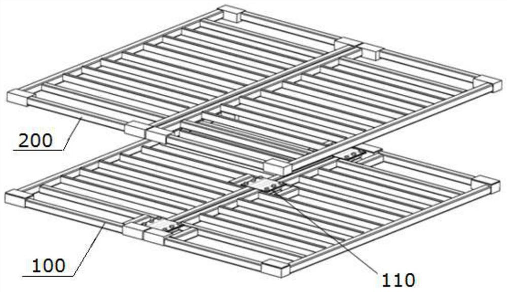
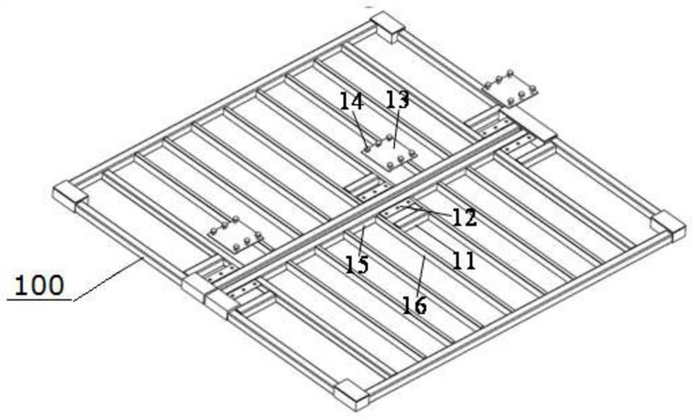
[0029] In one embodiment of the present invention, as Figure 1 to Figure 6 As shown, a detachable floor connection node for a modular steel structure, including a modular ceiling 100, a modular floor 200 and a ceiling beam connection assembly 110; wherein:

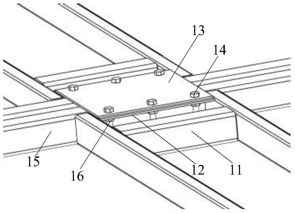
[0030] The ceiling beam connection assembly 110 includes a short beam 11, a beam connection plate 12, a horizontal connection cover plate 13 and high-strength bolts 14, the short beam 11 is pre-welded on the ceiling secondary beam 16, and the beam connection plate 12 is pre-welded Between the ceiling beams 15 and the short beams 11 that are horizontally connected, bolt holes 18 are reserved on the beam connecting plate 12, and the nuts 17 are fixed with a fixing device at the places wher...


PUM


Abstract

The invention discloses a detachable floor system connecting joint for a modular steel structure and a manufacturing method thereof. The connecting joint comprises modular ceilings, modular floor slabs and ceiling slab beam connecting assemblies. According to the detachable floor system connecting joint for the modular steel structure and the manufacturing method thereof, detachable floor system connecting structures are arranged at the joints between the adjacent modular ceiling slab beams, horizontal connection between modular units is enhanced, and the problems that when the modular units on the same layer are spliced, due to the fact that the floor slabs are discontinuous, the modular steel structure is excessively deformed in the plane, and the rigidity in the plane of the floor slabs is insufficient are solved; and meanwhile, the welding parts of the connecting structures are completed in a factory in advance, after the connecting structures are transported to the site, high-strength bolts are adopted for on-site assembly, no welding exists on the site, when the service life of the structure is due and the structure needs to be disassembled, the adjacent modular units can be separated by unscrewing the high-strength bolts, the overall stress performance of the modular steel structure can be considered on the premise that the assembly advantages of a modular building are exerted, and the integrity, construction convenience and detachability of the modular steel structure are guaranteed.

Description

technical field [0001] The invention belongs to the field of construction engineering, and in particular relates to a detachable floor connection node for a modular steel structure and a manufacturing method. Background technique [0002] The prefabricated steel structure system is a building unit or component manufactured according to uniform and standard building part specifications. It is a building produced after prefabricated production in the factory and then transported to the construction site for assembly. It has the advantages of energy saving, environmental protection, fast construction speed, and high degree of industrialization. The development of industrialized prefabricated steel structure system is an urgent requirement of my country's green building and building industrialization. Modular steel structure is a highly integrated prefabricated building. After prefabricating the beams, plates, columns, walls and other components in the modular units in the factor...

Claims


Application Information

Patent Timeline
Patent Type & Authority Applications(China)
IPC IPC(8): E04B5/02E04B5/10E04B5/14
CPCE04B5/02E04B5/10E04B5/14
Inventor 陈洋史奉伟丁阳娄霓宗亮周永安易国辉吴颖刘长松江海涛周永鹏朱进岳
Owner CIMC MODULAR BUILDING SYST HLDG CO LTD
Learn More