Slurry barrier strip for silk-screen printing and use method of slurry barrier strip

A technology of screen printing and paste, applied in screen printing, screen printing machine, printing and other directions, can solve the problems of large difference in junction depth and concentration, affecting current collection, affecting printing uniformity, etc., to improve the process Accuracy, uniform slurry distribution effect

Active Publication Date: 2021-05-28
CHANGZHOU SHICHUANG ENERGY CO LTD
View PDF5 Cites 0 Cited by
  • Summary
  • Abstract
  • Description
  • Claims
  • Application Information

AI Technical Summary

Problems solved by technology

[0003] like figure 1 As shown, in the case of long-term multi-batch printing, due to the deformation of the screen plate by the scraper, the screen plate will have a low middle part and a height difference on both sides, and the slurry is fluid. The slurry will flow slowly from the high position to the low position, resulting in more and more slurry in the middle of the screen, and less and less slurry on both sides of the screen. In the case of less material, when the scraper is pushed forward again, more paste will be squeezed out in the middle of the ...

Method used


Image

  • Slurry barrier strip for silk-screen printing and use method of slurry barrier strip
  • Slurry barrier strip for silk-screen printing and use method of slurry barrier strip
  • Slurry barrier strip for silk-screen printing and use method of slurry barrier strip

Examples


Embodiment Construction

[0028] The specific implementation manners of the present invention will be further described below in conjunction with the drawings and examples. The following examples are only used to illustrate the technical solution of the present invention more clearly, but not to limit the protection scope of the present invention.

[0029] The technical scheme of concrete implementation of the present invention is:

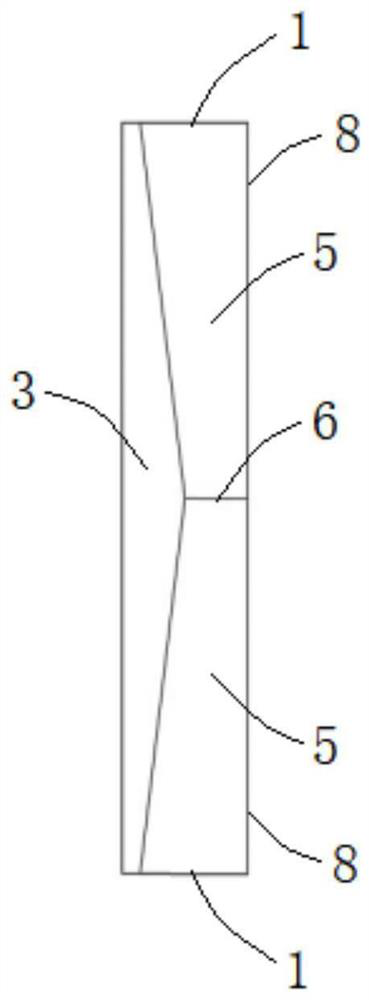
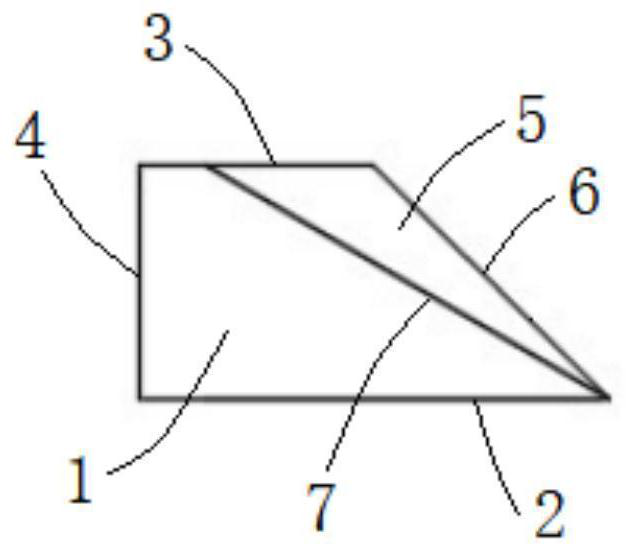
[0030] Such as Figure 2 to Figure 5 As shown, the present invention provides a paste retaining strip for screen printing, which includes a strip-shaped main body, and the strip-shaped main body includes: a pair of vertical end faces 1 arranged at both ends of the strip-shaped main body in the length direction, and located between the pair of end faces 1 The flat bottom surface 2 of the bottom surface 2, the slurry blocking surface located between the pair of end surfaces 1 and obliquely placed directly above the bottom surface 2, the flat top surface 3 located above the ...


PUM


Abstract

The invention discloses a slurry blocking strip for silk-screen printing. The slurry blocking strip comprises a pair of vertical end faces, a horizontal bottom face and a slurry blocking face obliquely arranged over the bottom face, and the slurry blocking face is composed of a pair of inclined faces. When the slurry blocking strip is used in silk-screen printing, slurry can be distributed more uniformly, and the process precision, uniformity and stability of silk-screen printing can be improved.

Description

technical field [0001] The invention relates to the technical field of screen printing, in particular to a paste bar for screen printing and a method for using the same. Background technique [0002] The screen printing machine mainly includes: printing head (including scraper, ink return knife), printing table, screen frame and so on. The screen plate is fixed on the screen frame, the screen plate is squeezed and deformed by the scraper, and the slurry on the screen plate is extruded out of the pattern, and then the slurry scraped by the scraper is scraped back to the original position by the ink return knife, and this is done once printing process. [0003] Such as figure 1 As shown, in the case of long-term multi-batch printing, due to the deformation of the screen plate by the scraper, the screen plate will have a low middle part and a height difference on both sides, and the slurry is fluid. The slurry will flow slowly from the high position to the low position, resu...

Claims


Application Information

Patent Timeline
IPC IPC(8): B41F15/34
CPCB41F15/36B41P2215/10
Inventor 奚琦鹏潘琦史卓群杨立功
Owner CHANGZHOU SHICHUANG ENERGY CO LTD
Why Eureka
Try Eureka