Stone cleaning and crushing integrated machine for building
An all-in-one machine and construction technology, which is applied in the direction of cleaning methods using liquids, dryers, and drying gas arrangements, can solve problems that affect the quality of construction and the combination of mixed soil is not firm.
- Summary
- Abstract
- Description
- Claims
- Application Information
AI Technical Summary
Problems solved by technology
Method used
Image
Examples
Embodiment 1
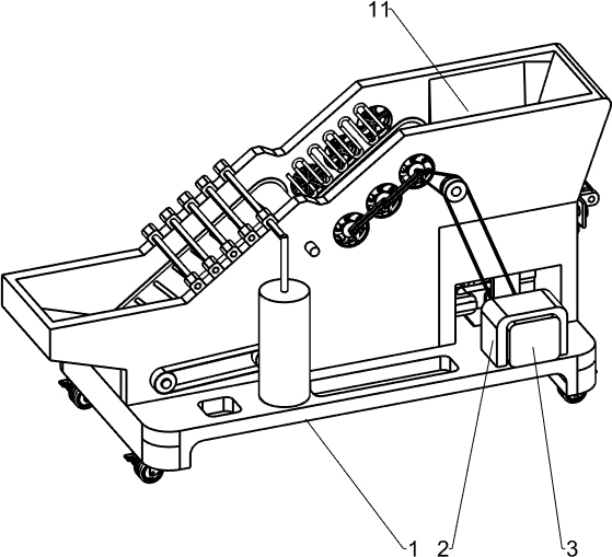
[0037] Such as Figure 1-3 As shown, a stone washing and crushing integrated machine for construction includes a cart 1, a mounting frame 2, a reduction motor 3, a housing 4, a vertical plate 5, a fixing seat 6, a first rotating shaft 7, a crushing mechanism 8 and a screening mechanism 9. The right side of the top of the trolley 1 is connected to the installation frame 2, and the installation frame 2 is provided with a geared motor 3 through bolts. The geared motor 3 is connected to the trolley 1, and the top of the trolley 1 behind the geared motor 3 is installed with a housing 4. A riser 5 is installed between the housing 4 and the top of the cart 1, a fixed seat 6 is installed on the top of the cart 1 on the rear side of the riser 5, and a first rotating shaft 7 is rotatably installed between the riser 5 and the fixed seat 6 , the front end of the first rotating shaft 7 is affixed to the rear end of the output shaft of the geared motor 3, the housing 4 is provided with a cr...
Embodiment 2
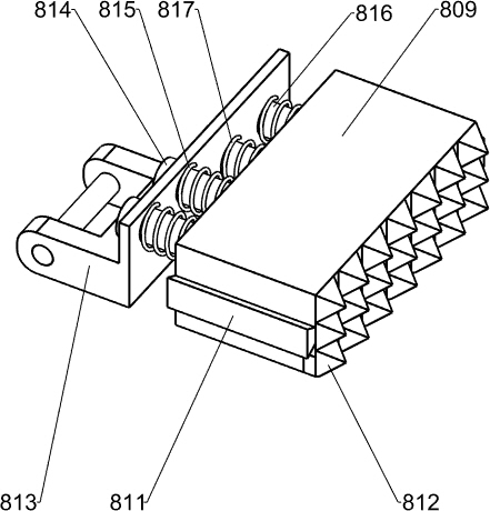
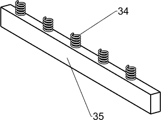
[0040] Such as Figure 1-6 As shown, on the basis of Embodiment 1, the crushing mechanism 8 includes a turret 801, a swing plate 802, a swing frame 803, a first slider 804, a fixed plate 805, a slide bar 806, a connecting plate 807, and a moving block 809 , the second slider 811, the crushing teeth 812, the moving frame 813, the first guide rod 814, the first spring 815, the second guide rod 816 and the second spring 817, the front and rear sides of the first rotating shaft 7 are all embedded with a rotating frame 801, on the turret 801, a swinging plate 802 is rotatably installed, on the swinging plate 802, a swinging frame 803 is rotatably installed, on the front and rear side walls of the swinging frame 803, a first slide block 804 is arranged, and the first slide block 804 and The housing 4 is slidably matched, and two fixing plates 805 are installed on the left and right side walls of the housing 4, and a slide bar 806 is installed between the two adjacent fixing plates 8...
Embodiment 3
[0045] Such as Figure 1-8 As shown, on the basis of Embodiment 2, it also includes a first pulley 10, a bracket 11, a second rotating shaft 12, a conveying roller 13, a conveying belt 131, a contact ring 132, a second pulley 14, a first belt 15. The third pulley 16 and the second belt 17, the first pulley 10 is installed on the output shaft of the reduction motor 3, the top of the trolley 1 on the left side of the housing 4 is equipped with a bracket 11, the bracket 11 is fixed with the housing 4 Then, four second rotating shafts 12 are rotatably installed between the front and rear side walls of the bracket 11, and conveying rollers 13 are installed on the second rotating shafts 12, and a conveying belt 131 is wound between two corresponding conveying rollers 13, The front and rear sides of the outer wall of the conveyor belt 131 are equipped with contact rings 132, the contact rings 132 cooperate with the support 11, the front ends of the two second rotating shafts 12 on th...
PUM
 Abstract
Description
Claims
Application Information
 - Generate Ideas
- Intellectual Property
- Life Sciences
- Materials
- Tech Scout
- Unparalleled Data Quality
- Higher Quality Content
- 60% Fewer Hallucinations
Browse by: Latest US Patents, China's latest patents, Technical Efficacy Thesaurus, Application Domain, Technology Topic, Popular Technical Reports.
© 2025 PatSnap. All rights reserved.Legal|Privacy policy|Modern Slavery Act Transparency Statement|Sitemap|About US| Contact US: help@patsnap.com


