
Oil sludge separation device

A technology of oil sludge separation and oil sludge, which is applied in separation methods, filtration separation, sludge treatment, etc., can solve the problems of high energy consumption, environmental pollution, and high cost, and achieve the effects of low energy consumption, cost reduction, and convenient material acquisition

Active Publication Date: 2021-05-28
SICHUAN UNIVERSITY OF SCIENCE AND ENGINEERING
View PDF9 Cites 0 Cited by
  • Summary
  • Abstract
  • Description
  • Claims
  • Application Information

AI Technical Summary

Problems solved by technology

Most of the oil sludge separation methods used at home and abroad are extraction methods, pyrolysis methods, and centrifugal separation methods. Most of them have problems such as high energy consumption, high cost, and serious environmental pollution.

Method used


Image

  • Oil sludge separation device
  • Oil sludge separation device
  • Oil sludge separation device

Examples


Embodiment Construction

[0027] In order to make the object, technical solution and advantages of the present invention clearer, the present invention will be further described in detail below in conjunction with the accompanying drawings. Apparently, the described embodiments are only some of the embodiments of the present invention, but not all of them. Based on the embodiments of the present invention, all other embodiments obtained by persons of ordinary skill in the art without making creative efforts belong to the protection scope of the present invention.

[0028] In the description of the present invention, it should be noted that the terms "center", "upper", "lower", "left", "right", "vertical", "horizontal", "inner", "outer" etc. The indicated orientation or positional relationship is based on the orientation or positional relationship shown in the drawings, and is only for the convenience of describing the present invention and simplifying the description, rather than indicating or implying...


PUM


Abstract

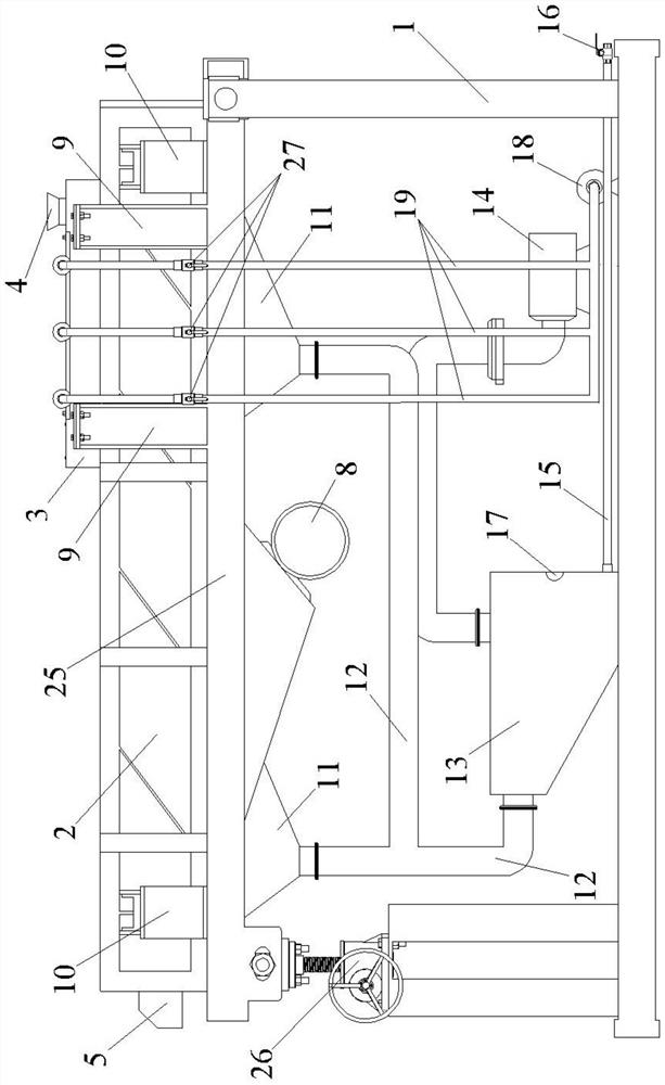
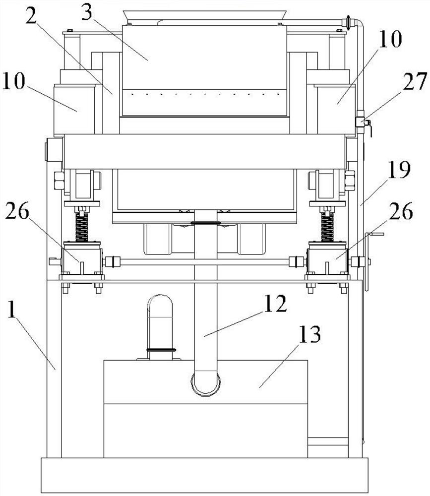
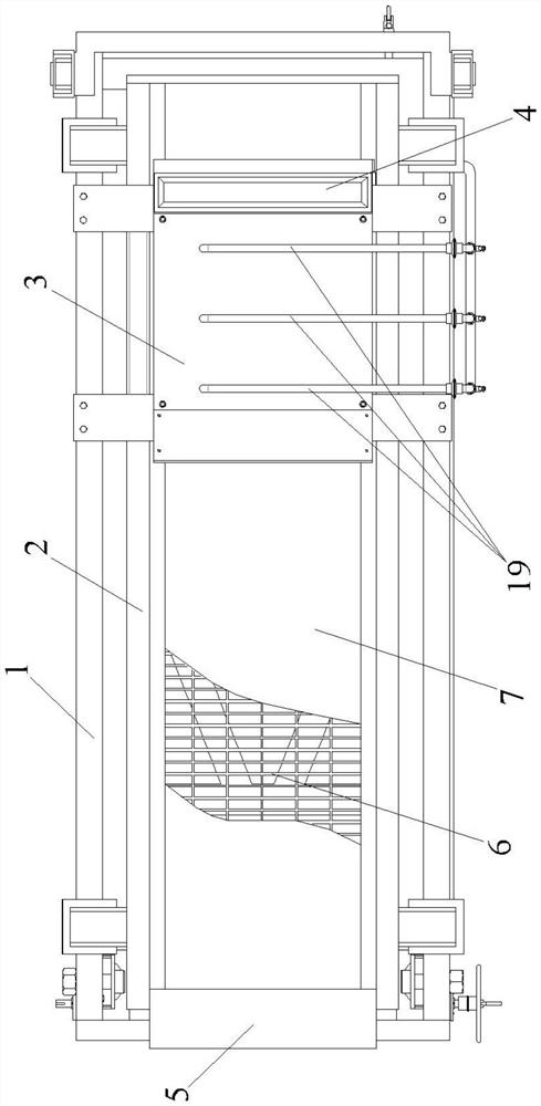
The invention discloses an oil-sludge separation device, which can effectively solve the technical problems that the separation efficiency is low and the environment is easily polluted during separation in the prior art. The device comprises a rack, wherein a vibration separation box which is mounted on the rack and is used for separating solid and liquid in the oil sludge, and a water jet box which is arranged in the vibration separation box and is communicated with the vibration separation box, the water jet box is provided with an oil sludge inlet used for adding oil sludge into the water jet box, the water jet box is connected with a high-pressure water column spraying mechanism used for generating high-pressure water columns in the water jet box to act on the oil sludge, and the vibration separation box is provided with a sludge outlet and further connected with a separated water discharging mechanism. The device is scientific and reasonable in design and convenient to use, wherein the oil sludge is dehydrated and separated in a water jet impact and vibration and negative pressure adsorption dehydration mode, so that the oil sludge separation efficiency can be effectively improved; in addition, the method is free of chemical solvents, so that the problem of environmental pollution caused by the prior art can be well solved, energy consumption can be effectively reduced, and oil sludge separation treatment cost is reduced.

Description

technical field [0001] The invention belongs to the technical field of oil sludge separation equipment, and in particular relates to an oil sludge separation device. Background technique [0002] Oil sludge is an unconventional oil resource with complex composition and oil content between 10% and 50%, which has the value of recycling. In order to effectively separate the sludge and recover the oil, it is necessary to adopt appropriate separation technology according to different sludge types. The separation mechanism of oil sludge is to remove the wrapping state of oil, sand and water through physical or chemical methods, so that oil, sand and water can be recovered separately after separation. Most of the oil sludge separation methods used at home and abroad are extraction methods, pyrolysis methods, and centrifugal separation methods. Most of them have problems such as high energy consumption, high cost, and serious environmental pollution. [0003] Therefore, the presen...

Claims


Application Information

Patent Timeline
Patent Type & Authority Applications(China)
IPC IPC(8): B01D36/00C02F11/00
CPCB01D36/008C02F11/00Y02W10/40
Inventor 陈林柳忠彬左清泽周国兵彭帝
Owner SICHUAN UNIVERSITY OF SCIENCE AND ENGINEERING
Learn More