
Silicon nitride ceramic substrate of copper-clad plate and preparation method thereof

A technology of copper clad laminate and nitrided ceramic silicon, which is applied in the field of silicon nitride ceramics and its preparation, and can solve the problems of reducing the effective life of devices and the like

Active Publication Date: 2021-05-18
SHANGHAI INST OF CERAMIC CHEM & TECH CHINESE ACAD OF SCI
View PDF7 Cites 4 Cited by
  • Summary
  • Abstract
  • Description
  • Claims
  • Application Information

AI Technical Summary

Problems solved by technology

For electronic devices, the effective life of the device will be reduced by 30% to 50% for every 10°C increase in temperature.

Method used


Image

  • Silicon nitride ceramic substrate of copper-clad plate and preparation method thereof
  • Silicon nitride ceramic substrate of copper-clad plate and preparation method thereof
  • Silicon nitride ceramic substrate of copper-clad plate and preparation method thereof

Examples


preparation example Construction

[0050] The preparation method of the silicon nitride ceramic material specifically comprises the following steps: mixing materials under a protective atmosphere and forming a green body, pretreatment under a reducing atmosphere, sintering under a nitrogen atmosphere and controlling the sintering system.

[0051] Mixing under protective atmosphere. The original powder, sintering aid Y 2 o 3 The powder and the MgO powder are added into an airtight container with absolute ethanol as a solvent, mixed evenly under the protection of a protective atmosphere, and then dried to obtain a mixed powder. Alternatively, the original powder, sintering aid Y 2 o 3 The powder and the MgO powder are placed in a closed container, then absolute ethanol is added as an organic solvent, PVB is used as a binder, and then mixed evenly under the protection of a protective atmosphere to obtain a mixed slurry. Wherein, the binder can be 5-9 wt% of the total mass of the original powder + sintering aid...

Embodiment 1

[0071] First, 95g Si 3 N 4 Powder, 5g sintering aid powder (Y 2 o 3 : MgO=1.2:2.5, molar ratio), 1g castor oil, 1g PEG, 70g absolute ethanol and 200g silicon nitride grinding balls are put into the lined polyurethane ball milling tank with atmosphere protection function, and after sealing the ball milling tank cover, pump them out sequentially. Vacuum, N 2 In a protective atmosphere, the slurry was obtained after ball milling and mixing for 6 hours; 5g PVB and 3g DBP were further added to the above slurry, and the 2 Under the protection of the atmosphere, the uniform slurry was obtained after ball milling for 6 hours; secondly, the slurry was vacuum degassed for 6 hours, and the 2 Under the protection of the atmosphere, the substrate green body is tape-casted, and the thickness of the substrate green body is d±0.05mm (d=0.2~2.0); again, the formed substrate green body is cut into the required shape and placed in a BN crucible, and It is packed into a carbon tube furnace; ...

Embodiment 2~5

[0074] Specific parameters such as the ratio of raw materials, composition of sintering aids, pretreatment process, and sintering process are shown in Table 1. The process refers to Example 1. The composition and properties of the prepared materials are shown in Table 2.


PUM

PropertyMeasurementUnit
thicknessaaaaaaaaaa
thicknessaaaaaaaaaa
particle sizeaaaaaaaaaa

Abstract

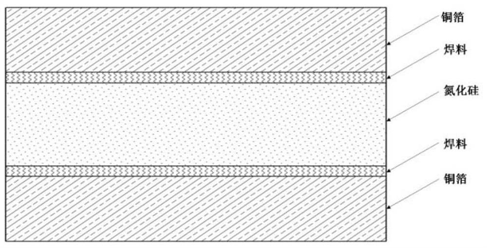
The invention relates to a silicon nitride ceramic substrate of a copper-clad plate and a preparation method thereof. The silicon nitride ceramic substrate of the copper-clad plate structurally comprises a silicon nitride ceramic substrate, copper plates distributed on the upper side and the lower side of the silicon nitride ceramic substrate, and welding layers distributed between the copper plates and the silicon nitride ceramic substrate. The components of the ceramic nitride silicon ceramic substrate comprise a silicon nitride phase and a grain boundary phase; the content of the silicon nitride phase is greater than or equal to 95 wt%; the grain boundary phase is a mixture at least containing three elements of Y, Mg and O; the content of the grain boundary phase is less than or equal to 5wt%, and the content of the crystal phase in the grain boundary phase is greater than or equal to 40vol%.

Description

technical field [0001] The invention relates to a copper-clad silicon nitride ceramic and a preparation method thereof, which belong to the field of semiconductor materials and devices. Background technique [0002] In recent years, semiconductor devices have developed rapidly along the direction of high power, high frequency, and integration. The heat generated by the operation of semiconductor devices is the key factor causing the failure of semiconductor devices, and the thermal conductivity of the insulating substrate is the key to affecting the overall heat dissipation of semiconductor devices. In addition, in fields such as electric vehicles, high-speed railways, and rail transit, semiconductor devices often face complex mechanical environments such as bumps and vibrations during use, which imposes strict requirements on the reliability of the materials used. [0003] High thermal conductivity silicon nitride (Si 3 N 4 ) Ceramics are considered to be the best semico...

Claims


Application Information

Patent Timeline
Patent Type & Authority Applications(China)
IPC IPC(8): C04B37/02
CPCC04B37/003C04B2237/125C04B37/026C04B2237/368C04B2237/407C04B35/584C04B35/587C04B35/591C04B35/5935C04B35/6342C04B2235/6567C04B2235/6562C04B2235/661C04B2235/6582C04B2235/783C04B2235/786C04B2235/6025C04B2235/3225C04B2235/3206C04B2235/428C04B2235/3882C04B2235/85C04B2237/124C04B2237/127C04B2235/6581C04B2237/74C04B37/006
Inventor 刘学建张辉姚秀敏刘岩蒋金弟黄政仁陈忠明
Owner SHANGHAI INST OF CERAMIC CHEM & TECH CHINESE ACAD OF SCI
Learn More