
Heat dissipation device for electric power engineering equipment

A technology for heat dissipation of equipment and power engineering, applied in the direction of cooling/ventilation of substations/switchgears, etc., can solve problems such as unfavorable saving of water resources, inability to reduce the temperature of power equipment, etc.

Inactive Publication Date: 2021-05-14
郭振宇
View PDF1 Cites 0 Cited by
  • Summary
  • Abstract
  • Description
  • Claims
  • Application Information

AI Technical Summary

Problems solved by technology

[0002] Power equipment mainly includes power generation equipment and power supply equipment. Especially in thermal power plants, because some power equipment is close to high-temperature equipment such as boilers, it is necessary to use heat dissipation to cool down the power equipment to ensure the safety of power equipment. The invention patent with the patent application number CN201911334918.9 discloses a heat dissipation device for electric power equipment. The existing heat dissipation device for electric power equipment basically has a variety of structures, can meet the heat dissipation needs of power equipment of different sizes and types, and is easy to install and fix. , firm structure, long service life, etc., can meet the requirements for the use of heat dissipation for various power equipment. However, for the existing heat dissipation devices for power equipment, on the one hand, when the power equipment is in a high temperature The air temperature is high, which leads to the inability of the high temperature in the power equipment to be dissipated, which in turn cannot reduce the temperature of the power equipment, which is not conducive to ensuring the safety of the power equipment. On the other hand, when using spray water to cool the cooling gas , in order to prevent moisture from endangering the safety of power equipment, it is often necessary to use heat transfer equipment, use spray water to cool the heat exchange equipment, and then use the heat exchange equipment to cool the cooling gas, which not only increases equipment investment, but also reduces the efficiency of air conditioning, and on the other hand, when using When the spray water cools the cooling gas, a large amount of spray water will be volatilized, and the dust contained in the cooling gas will pollute the water, requiring frequent replacement of new water sources, which is not conducive to saving water resources

Method used


Image

  • Heat dissipation device for electric power engineering equipment
  • Heat dissipation device for electric power engineering equipment
  • Heat dissipation device for electric power engineering equipment

Examples


Embodiment approach

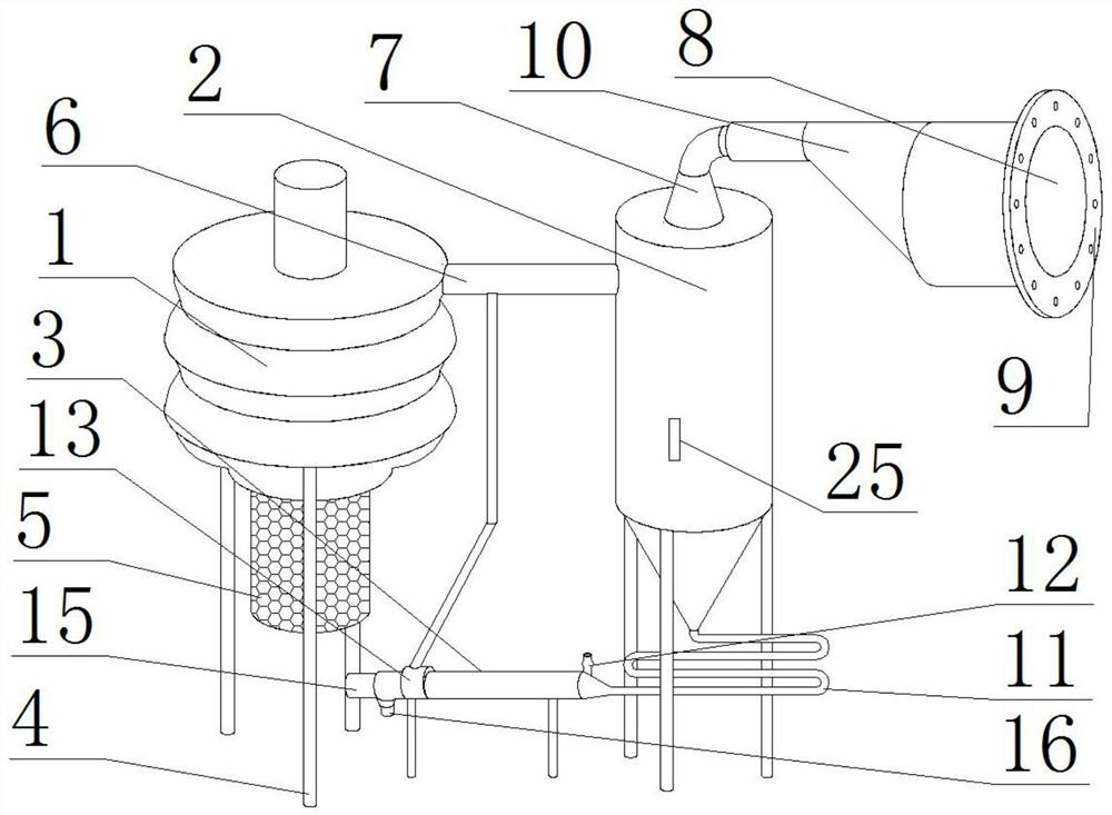
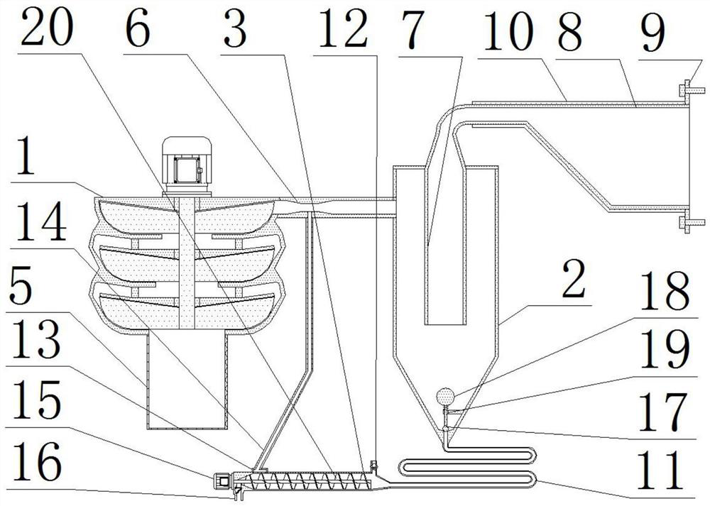
[0025]As a preferred embodiment of the present invention, the high-pressure fan 1 communicates with one side of the cyclone 2 through the Venturi tube 6, and the bottom end of the outlet pipe 7 passes through the cyclone 2 and extends to the bottom of the cyclone 2. In the middle part, the high-pressure air forms a high-speed airflow in the middle of the Venturi tube 6. At this time, the water is dispersed and atomized by the high-speed airflow in the Venturi tube 6, and after fully contacting with the high-temperature air, the water mist can absorb the heat in the high-temperature air , to cool down the high temperature gas.

[0026] As a preferred embodiment of the present invention, the bottom of the cyclone 2 is provided with a through hole, the cyclone 2 communicates with the heat dissipation pipe 11 through the through hole, and the bottom end of the plug 17 is stuck in the through hole. top.

[0027] As a preferred embodiment of the present invention, one side of the s...


PUM


Abstract

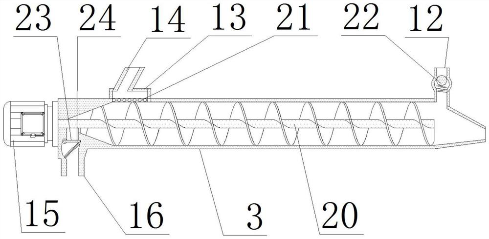
The invention provides a heat dissipation device for electric power engineering equipment. The device comprises a high-pressure fan, a cyclone cylinder and a sleeve, a separation net is installed at the bottom of the high-pressure fan through bolts, a Venturi tube is welded to one side of the high-pressure fan, an outlet pipe is welded to the top of the cyclone cylinder, a conical barrel is welded to one end of the outlet pipe, a fixing plate is welded to one side of the conical barrel, a heat preservation sleeve is arranged on the outer side of the conical barrel in a sleeving mode, and a heat dissipation pipe is welded to the bottom of the cyclone cylinder. The heat dissipation device for the electric power engineering equipment can cool the electric power engineering equipment after the air temperature is reduced to be below the cooling air temperature needed by the electric power engineering equipment. The cooling efficiency of the electric power engineering equipment in a high-temperature environment is guaranteed, the problem that direct contact between water and air cannot be utilized for heat exchange is solved, the heat exchange efficiency is improved, water mist is prevented from entering the electric power engineering equipment, cyclic utilization of water is guaranteed, consumption of the water is reduced, and the heat dissipation device is suitable for heat dissipation of the electric power engineering equipment.

Description

technical field [0001] The invention relates to the technical field of heat dissipation devices for electric power equipment, in particular to a heat dissipation device for electric power engineering equipment. Background technique [0002] Power equipment mainly includes power generation equipment and power supply equipment. Especially in thermal power plants, because some power equipment is close to high-temperature equipment such as boilers, it is necessary to use heat dissipation to cool down the power equipment to ensure the safety of power equipment. The invention patent with the patent application number CN201911334918.9 discloses a heat dissipation device for electric power equipment. The existing heat dissipation device for electric power equipment basically has a variety of structures, can meet the heat dissipation needs of power equipment of different sizes and types, and is easy to install and fix. , firm structure, long service life, etc., can meet the requireme...

Claims


Application Information

Patent Timeline
IPC IPC(8): H02B1/56
CPCH02B1/56
Inventor 郭振宇
Owner 郭振宇
Learn More