
Sewage treatment device with multi-mode operation

A sewage treatment device, multi-mode operation technology, applied in multi-stage water treatment, biological water/sewage treatment, water/sewage multi-stage treatment, etc. And/or total phosphorus treatment to meet the standard and other issues

Pending Publication Date: 2021-05-14
北京安国水道自控工程技术有限公司
View PDF0 Cites 1 Cited by
  • Summary
  • Abstract
  • Description
  • Claims
  • Application Information

AI Technical Summary

Problems solved by technology

[0005] After long-term research, the inventor of the present application found that the secondary biochemical reaction tank of the existing sewage plant cannot treat the total nitrogen and / or total phosphorus in the water body due to the single operation mode when the influent water quality and / or influent water volume change. standard question
By changing the single operation mode of the traditional biochemical pool, a multi-mode operation sewage treatment device that can adjust the operation mode according to the change of influent water quality and / or influent water volume and provide guarantee for dephosphorization is developed, that is, it can realize multi-mode The operating biological nitrogen and phosphorus removal multifunctional biochemical pool, thus solving the problem that the traditional process of sewage treatment biological nitrogen and phosphorus removal cannot meet the discharge standards at the same time

Method used


Image

  • Sewage treatment device with multi-mode operation
  • Sewage treatment device with multi-mode operation
  • Sewage treatment device with multi-mode operation

Examples


Embodiment 1

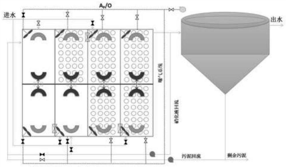
[0027] Operation mode one: anaerobic-aerobic (A P / O). Such as figure 2 As shown, open the water inlet valve V1, so that the sewage after the primary treatment of the sewage plant enters the anaerobic state (by closing the aeration valve AV1 corresponding to this small reverse tank, the anaerobic state is achieved, the same below) small reaction tank T1, in Under the impetus of the submersible flowmaker (M)) in the small reaction tank, the anaerobic (by closing the aeration valve AV2 corresponding to the small reaction tank to reach the anaerobic state, the same below) the small reaction tank T2, the anaerobic ( By closing the aeration valve AV3 corresponding to this small reaction tank, the anaerobic state is achieved, the same below) small reaction tank T3. The small reaction pools T1, T2, and T3 are connected through water holes at the bottom. At the same time, turn on the sludge return pump (P2) and return valve (RV3) of the system to return a certain amount of activat...

Embodiment 2

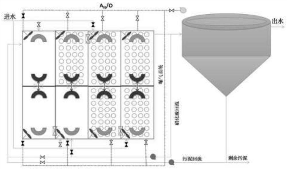
[0030]Operation mode two: anoxic-aerobic (A N / O). Such as image 3 As shown, open the water inlet valve V1, so that the sewage after the primary treatment of the sewage plant enters the anoxic state (by closing the aeration valve AV1 corresponding to this small reverse tank, the anoxic state is reached, the same below) small reaction tank T1, in Under the impetus of the submersible flowmaker (M) in the small reaction tank, the small reaction tank T2, the hypoxia (through Close the aeration valve AV3 corresponding to this small reaction tank to reach anoxic state, the same below) small reaction tank T3. The small reaction pools T1, T2, and T3 are connected through water holes at the bottom. At the same time, turn on the nitrification liquid return pump (P1), sludge return pump (P2) and return valve (RV2, RV3) of the system to transfer a certain amount of NO 3 -N and NO 2 -N aerobic tank mixed liquid is returned to the anoxic small reaction tank T1 to prepare for the denit...

Embodiment 3

[0033] Operation mode three: anaerobic-anoxic-aerobic (A / A / O). Such as Figure 4 As shown, open the water inlet valve V1, so that the sewage after the primary treatment of the sewage plant enters the anaerobic state (by closing the aeration valve AV1 corresponding to this small reverse tank, the anaerobic state is achieved, the same below) small reaction tank T1, in Under the impetus of the submersible flowmaker (M) in the small reaction tank, it enters the anaerobic (by closing the aeration valve AV2 corresponding to the small reaction tank, the anaerobic state is reached, the same below) small reaction tank T2. Afterwards, the sewage enters the anoxic (by closing the aeration valve AV3 corresponding to this small reverse tank, to reach the anoxic state, the same below) the small reaction tank T3, and under the impetus of the submersible flowmaker (M) in the small reaction tank, enters Hypoxia (by closing the aeration valve AV4 corresponding to this small reaction tank, the ...


PUM


Abstract

The invention discloses a sewage treatment device with multi-mode operation, and belongs to the field of sewage treatment systems. Four groups of fixed tank bodies are arranged in parallel, and a fixed flow guide wall, a movable flow guide device, an aeration device and the like are respectively arranged at two ends of each group of fixed tank bodies. The volume distribution of different reaction tanks can be realized by the movable flow guide device, so that the optimal nitrogen and phosphorus removal treatment effect is achieved. Aeration devices are distributed on the whole tank body, and whether aeration of each area is started or not is controlled through valves on the aeration devices, so that the aerobic / anoxic / anaerobic state is realized. A step-feed multi-stage A / O operation mode is adopted, so that biological denitrification is enhanced, a carbon source in sewage is utilized to the greatest extent, internal reflux is not needed, and energy consumption is reduced. The system sludge concentration is higher than that of a traditional biochemical pool. Multiple modes can be alternately operated according to the water quality condition, and the number of the alternate operation modes can be as high as 7; the operation modes are diversified, switching is flexible and convenient, and the system can adapt to great changes of inflow water quality and meet the requirements of outflow water quality.

Description

technical field [0001] The invention relates to a sewage treatment device, which belongs to the field of sewage treatment systems, in particular to a biological nitrogen and phosphorus removal reaction device capable of realizing multi-mode operation. Background technique [0002] In recent years, sewage treatment has entered the stage of advanced treatment that not only efficiently removes organic matter but also efficiently removes nitrogen and phosphorus. The most common A / O is a biological treatment process developed by researchers for anoxic denitrification or anaerobic phosphorus release. The mixed solution is returned to the anoxic tank at the front end or the activated sludge is returned to the anaerobic tank at the front end, and the carbon source of the sewage is used to carry out the denitrification and denitrification process or the phosphorus removal process. In order to meet the requirements of simultaneous denitrification and phosphorus removal, people have d...

Claims


Application Information

Patent Timeline
IPC IPC(8): C02F3/02C02F3/30C02F3/34C02F9/14
CPCC02F3/02C02F3/30C02F3/34C02F9/00C02F2301/08Y02W10/10
Inventor 夏阁遥
Owner 北京安国水道自控工程技术有限公司
Learn More