Tapered roller bearing retainer automatic positioning mechanism and control method thereof

A tapered roller bearing, automatic positioning technology, applied in the direction of shafts and bearings, bearing components, positioning devices, etc., can solve problems such as offset, easily damaged molds, and no mold protection function, so as to improve product quality and maintain stability Effect

Inactive Publication Date: 2021-05-14
宁波致泰自动化装备有限公司
View PDF7 Cites 0 Cited by
  • Summary
  • Abstract
  • Description
  • Claims
  • Application Information

AI Technical Summary

Problems solved by technology

[0003] 1. The loading and positioning of the tapered roller bearing cage is not accurate. Because the tapered roller bearing cage is closely matched with the lower die of the punching press, the tapered roller bearing cage has burrs and stamping deformation in the previous process, resulting in conical roller bearing cage. When the roller bearing cage is put into the lower mold of the press slope, it will not be put in place or the position will be shifted when it is put in. When the manual operation cage is put into the lower mold of the punch press, it needs to be rotated left and right to align with the groove of the lower mold. After stamping, the operator needs to hold a screwdriver to pry to get rid of the lower mold. Therefore, there is no automatic equipment on the market that uses precision molds to press the slope of the tapered roller bearing cage.
[0004] 2. The automatic loading and unloading equipment for stamping tapered roller bearing cages using molds with low precision requirements on the market cannot automatically identify defective products, and the position of the product is shifted during automatic placement or the product is stuck on the upper mold. Unable to automatically identify, easy to damage the mold, no mold protection function

Method used


Image

  • Tapered roller bearing retainer automatic positioning mechanism and control method thereof
  • Tapered roller bearing retainer automatic positioning mechanism and control method thereof
  • Tapered roller bearing retainer automatic positioning mechanism and control method thereof

Examples


Embodiment Construction

[0031] The specific implementation manners of the present invention will be further described in detail below in conjunction with the accompanying drawings and embodiments. The following examples are used to illustrate the present invention, but are not intended to limit the scope of the present invention.

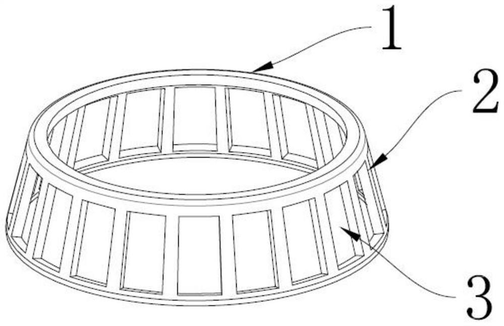
[0032] Such as Figure 1 to Figure 4 As shown, the automatic positioning mechanism of the tapered roller bearing cage of the present invention, it has been explained in advance that the tapered roller bearing cage 1 is the product to be positioned, and it is umbrella-shaped as a whole, and has regularly distributed ribs 2, Adjacent ribs 2 see hollowed-out windows 3 .

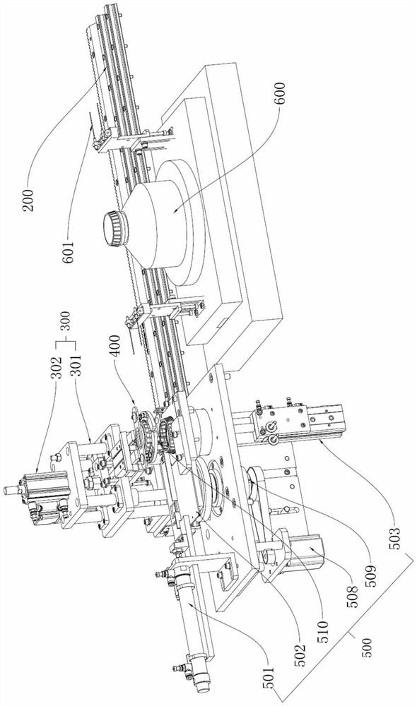
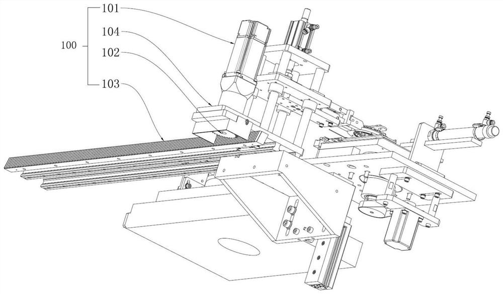
[0033] This mechanism includes servo transfer mechanism 100, slide rail 200, lifting mechanism 300, gripper mechanism 400, product positioning mechanism 500 and lower mold 600, wherein, lifting mechanism 300 is fixedly connected with servo transfer mechanism 100, and servo transfer mechanism 100 drives The...


PUM


Abstract

The invention discloses a tapered roller bearing retainer automatic positioning mechanism and a control method thereof. The tapered roller bearing retainer automatic positioning mechanism comprises a servo transfer mechanism, a sliding rail, a lifting mechanism, a gripper mechanism, a product positioning mechanism and a lower die, wherein the lifting mechanism is fixedly connected with the servo transfer mechanism, and the servo transfer mechanism drives the lifting mechanism to linearly move through the sliding rail; the gripper mechanism comprises a Z-shaped pneumatic gripper, the tail end of the Z-shaped pneumatic gripper is connected with a lifting mechanism, and the front end of the Z-shaped pneumatic gripper is connected with a profiling gripper. According to the technical scheme, the tapered roller bearing retainer automatic positioning mechanism has the following advantages that 1, an automatic feeding and discharging function is achieved when a precision mold is used in a slope pressing procedure of the tapered roller bearing retainer; and 2, the tapered roller bearing retainer automatic positioning mechanism can automatically identify defective products, the product quality is improved, the positioning precision is up to 100%, the problems that a mold is damaged and a retainer is scrapped after a slope is pressed due to positioning deviation of 0.01 mm are solved, and stability and continuity of automatic production are kept.

Description

technical field [0001] The invention relates to an automatic positioning mechanism for a tapered roller bearing cage and a control method thereof. Background technique [0002] According to the market survey: In the tapered roller bearing cage punching slope pressing process, for the use requirements of using precision molds to stamp the tapered roller bearing cage, the domestically produced tapered roller bearing cage slope pressure process has been carried out manually operation, it is impossible to realize the automatic loading and unloading of the tapered roller bearing cage pressing slope process. The main flaws in our analysis of this structure are: [0003] 1. The loading and positioning of the tapered roller bearing cage is not accurate. Because the tapered roller bearing cage is closely matched with the lower die of the punching press, the tapered roller bearing cage has burrs and stamping deformation in the previous process, resulting in conical roller bearing cag...

Claims


Application Information

Patent Timeline
Patent Type & Authority Applications(China)
IPC IPC(8): B21D43/00B21D43/10B21D53/12B21C51/00
CPCB21D43/003B21D43/105B21D53/12B21C51/00
Inventor 刘向荣姜小英
Owner 宁波致泰自动化装备有限公司
Why Eureka
Try Eureka