
Method of forming a perovskite film for an optoelectronic device

A technology for optoelectronic devices and perovskites, which is applied in the fields of electric solid devices, capacitors, photovoltaic power generation, etc., can solve the problem of not developing high-quality 2D perovskite film scalable technology, organic cations prone to hydrolysis reactions, affecting the device. performance issues

Pending Publication Date: 2021-05-11
COMMONWEALTH SCI & IND RES ORG
View PDF0 Cites 0 Cited by
  • Summary
  • Abstract
  • Description
  • Claims
  • Application Information

AI Technical Summary

Problems solved by technology

Disadvantages of 3D perovskites include low environmental stability due to weak photoinduced interactions between organic cations and surrounding halide anions, and the susceptibility of organic cations to hydrolysis reactions upon exposure to moisture.
However, the slot-die coating technique is not suitable for the production of many desired film shapes, and the quality control of perovskite films remains a challenge.
In principle, printing techniques offer greater flexibility in terms of perovskite film shape, but control of perovskite film thickness is challenging due to the difficulty in precise and consistent loading of printing precursor solutions over target areas. of
In addition, the printed precursor solution is prone to coalesce on the substrate before drying, which complicates the generation of finely resolved and tightly positioned perovskite film features.
[0008] For 2D perovskite films, the scaling challenge is considered to be particularly severe, since the orientation of the 2D crystalline slabs in the film affects device performance.
To date, no satisfactory scalable technique for fabricating high-quality 2D perovskite films has been developed

Method used


Image

  • Method of forming a perovskite film for an optoelectronic device
  • Method of forming a perovskite film for an optoelectronic device
  • Method of forming a perovskite film for an optoelectronic device

Examples


Embodiment approach

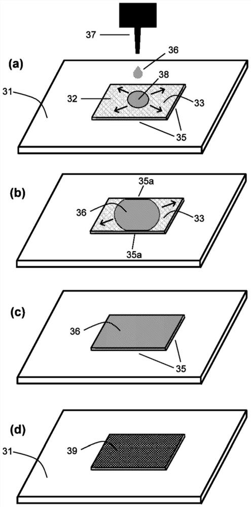
[0122] will now refer to figure 2 Embodiments of the present invention are described. As described herein, a hydrophilic layer 32 (eg, a printed PEDOT:PSS coating of about 30 nm thickness) is selectively positioned on a hydrophobic substrate 31 (eg, a PET film). Thus, the surface of the hydrophilic layer 32 presents a rectangular hydrophilic region 33 delimited by hydrophobic boundaries 35 formed by adjacent regions of the substrate 31 .

[0123] Substrate 31 is heated to a temperature of about 60°C to 70°C, for example by a heated backing plate (not shown). Such as figure 2 As shown in (a), the perovskite precursor solution 36 is then drop-coated from an applicator 37 (such as a needle) onto the central portion 38 of the hydrophilic region 33 . The perovskite precursor solution 36 may be a 2D perovskite precursor solution, for example, PbI in a molar ratio of 4:3:2 in DMF 2 , MAI and BAI solutions with a Pb concentration of about 0.3 mol / liter. Due to the hydrophilicit...

Embodiment 1

[0149] Embodiment 1. Preparation of perovskite precursor solution

[0150] 2D perovskite (BA) was prepared by 2 (MA) 3 Pb 4 I 13 Precursor solution: PbI with a molar ratio of 4:3:2 in dimethylformamide (DMF) at 70 °C 2 , MAI and BAI were stirred for 1 hour. Prepare Pb in this way 2+ The concentration is 0.9mol L -1 , 0.7mol L -1, 0.5mol L -1 , 0.3mol L -1 and 0.2mol L -1 The solution.

[0151] 2D perovskite (iso-BA) was prepared by 2 (MA) 4 Pb 5 I 16 Precursor solution: PbI with a molar ratio of 5:4:2 in dimethylformamide (DMF) at 70 °C 2 , MAI and isobutylammonium iodide (iso-BAI) were stirred for 1 hour. Prepare Pb in this way 2+ The concentration is 0.3mol L -1 The solution.

[0152] 2D perovskite (BA) was prepared by 2 (MA) 4 Pb 5 I 16 Precursor solution: PbI with a molar ratio of 5:4:2 in dimethylformamide (DMF) at 70 °C 2 , MAI and BAI were stirred for 1 hour. Prepare Pb in this way 2+ The concentration is 0.3molL -1 The solution.

[0153] 2D ...

Embodiment 2

[0156] Example 2. Preparation of shaped 2D perovskite films on glass substrates

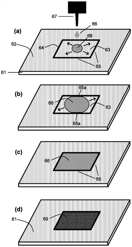
[0157] Use a size of 21G×1 1 / 4 A laboratory syringe needle, using an automatic pump to control the flow rate, draws a line of fluid composition onto the surface of an ITO glass substrate. The needle thus deposited a line of ink comprising the hydrophobic poly(triarylamine) (PTAA) polymer poly[bis(4-phenyl)(2,4,6-trimethylphenyl)amine on the substrate. The glass substrate has a hydrophilic surface characterized by a water contact angle of 36°±1.7. The water contact angle of PTAA exceeds 90° (about 105° reported in Nat Commun. 2015, 6, 7747). By drawing boundary lines on the surface of a hydrophilic substrate with a hydrophobic ink, it is possible to selectively cover shaped regions of the surface with a perovskite precursor solution by the following method.

[0158] The substrate was placed on a hot plate in air and heated to 50°C. Then Pb 2+ The concentration is 0.3mol L -1 of (BA) 2 (M...


PUM

PropertyMeasurementUnit
viscosityaaaaaaaaaa
thicknessaaaaaaaaaa
thicknessaaaaaaaaaa

Abstract

The invention provides a method of forming a perovskite film for an optoelectronic device, the method comprising: applying a perovskite precursor solution to at least one part of a hydrophilic region of a substrate, wherein the hydrophilic region is bounded by a hydrophobic boundary; allowing the perovskite precursor solution to spread over the hydrophilic region, wherein the perovskite precursor solution is retained within the hydrophilic region by at least a portion of the hydrophobic boundary; and drying the perovskite precursor solution to form a perovskite film on the hydrophilic region.

Description

technical field [0001] The present invention relates to methods of forming perovskite films for use in optoelectronic devices. The method includes applying a perovskite precursor solution to at least a portion of a hydrophilic region of a substrate, and drying the perovskite precursor solution to form a perovskite film on the hydrophilic region. When a perovskite solution is applied, in response to the adhesive force between the solution and the surface of the hydrophilic region, the perovskite solution can spread over the hydrophilic region and can remain in the hydrophilic region by defining the hydrophobic boundary of the hydrophilic region. within the water area. The invention also relates to a system comprising a substrate comprising a hydrophilic region, and an applicator for applying a perovskite precursor solution to at least a portion of the hydrophilic region. [0002] Background of the invention [0003] Thin-film solar cells including perovskite light-absorbing ...

Claims


Application Information

Patent Timeline
Patent Type & Authority Applications(China)
IPC IPC(8): H01L51/42H01L27/30H01L51/44
CPCH01L31/0264H01G9/20H01G9/2059H10K71/12H10K71/40H10K30/00Y02E10/542Y02E10/549H10K71/191H10K71/50H10K30/20H10K85/50H01L31/0256C07F7/24H10K30/10H01G9/0036H01G9/2009H10K30/30H10K85/30H10K85/111H10K85/215H10K85/1135
Inventor 高梅左传天D·瓦克
Owner COMMONWEALTH SCI & IND RES ORG
Learn More