
Air compressor for automobile braking system

A technology of automobile braking system and air compressor, applied in machine/engine, pump control, mechanical equipment, etc., can solve the problems of air compressor fatigue and wear, increasing motor workload on electric vehicles, and motor power output loss, etc.

Inactive Publication Date: 2021-05-11
胡东风
View PDF0 Cites 0 Cited by
  • Summary
  • Abstract
  • Description
  • Claims
  • Application Information

AI Technical Summary

Problems solved by technology

[0006] The invention provides an air compressor for an automobile braking system, which can automatically control the on-off connection between the air compressor and the motor spindle according to the pressure of the air storage tank, and the design stability and reliability of the purely mechanized mechanism are high. , effectively reducing the power loss of the motor spindle on it and the fatigue wear of the air compressor, and solving the problem of setting the air compressor on the existing electric vehicle, the power shaft is connected with the motor spindle on the electric vehicle, As long as the motor on the electric vehicle starts to work, it will drive the air compressor to work together, which not only increases the working load of the motor on the electric vehicle, but also needs to set a pressure control valve on the air storage tank to adjust the pressure in it. Furthermore, when the air storage tank is fully loaded, the power output loss of the motor is caused. At the same time, the air compressor always operates together with the motor shaft, which is very easy to cause fatigue and wear to the air compressor and affect its service life.

Method used


Image

  • Air compressor for automobile braking system
  • Air compressor for automobile braking system
  • Air compressor for automobile braking system

Examples


Embodiment Construction

[0021] The following will clearly and completely describe the technical solutions in the embodiments of the present invention with reference to the accompanying drawings in the embodiments of the present invention. Obviously, the described embodiments are only some, not all, embodiments of the present invention. Based on the embodiments of the present invention, all other embodiments obtained by persons of ordinary skill in the art without making creative efforts belong to the protection scope of the present invention.

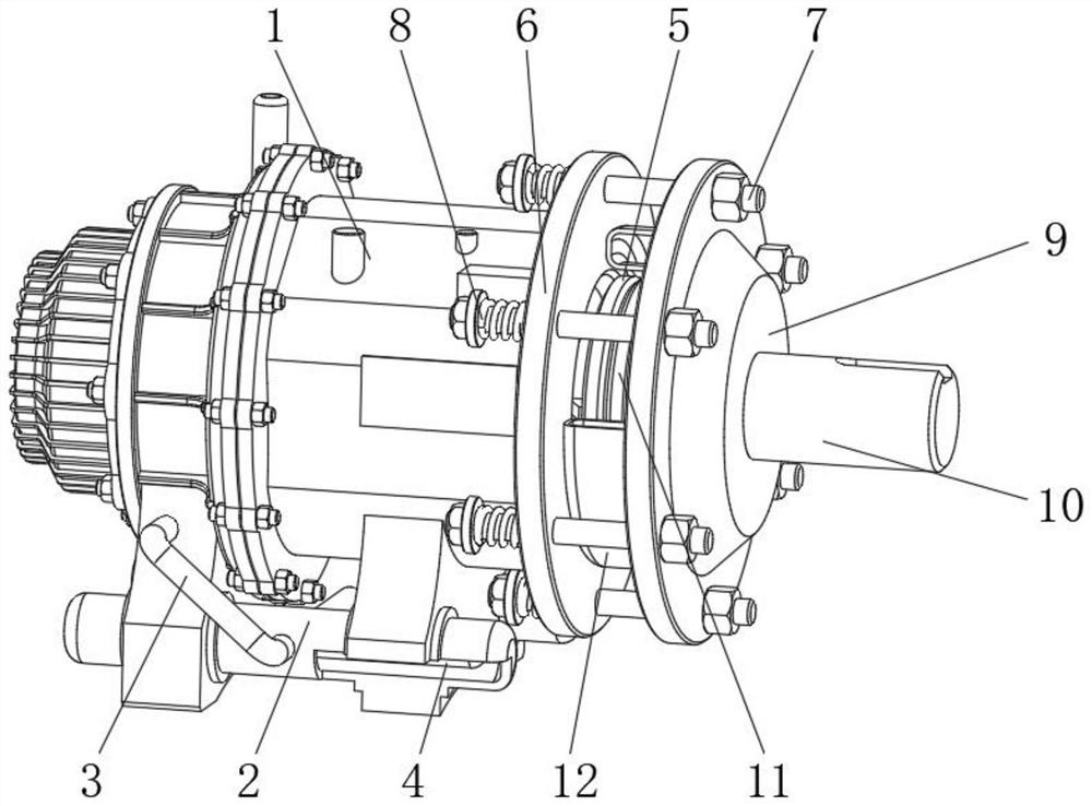
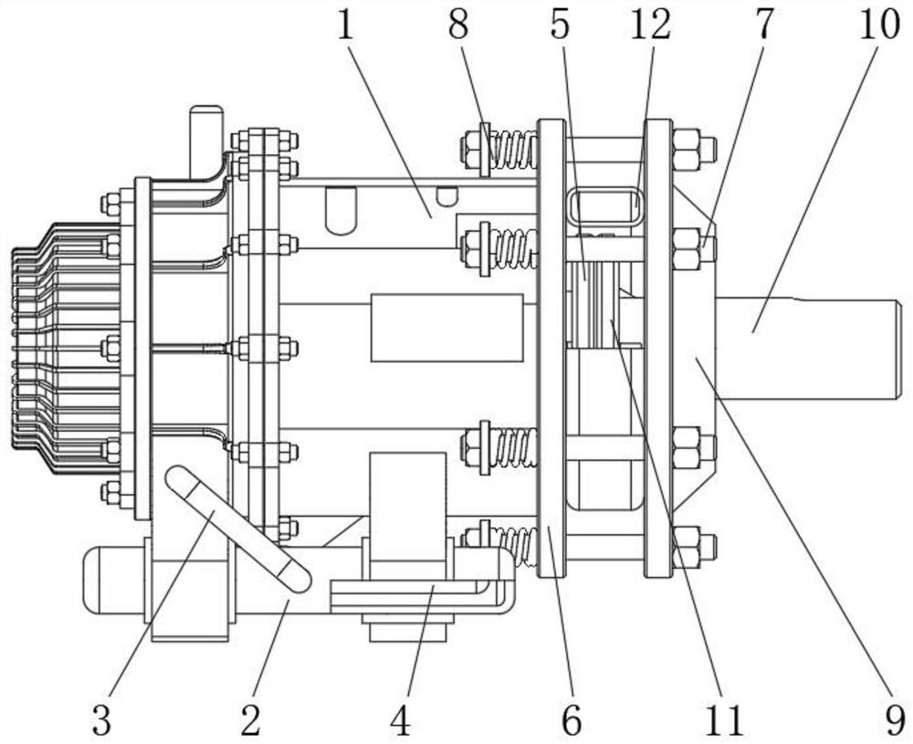
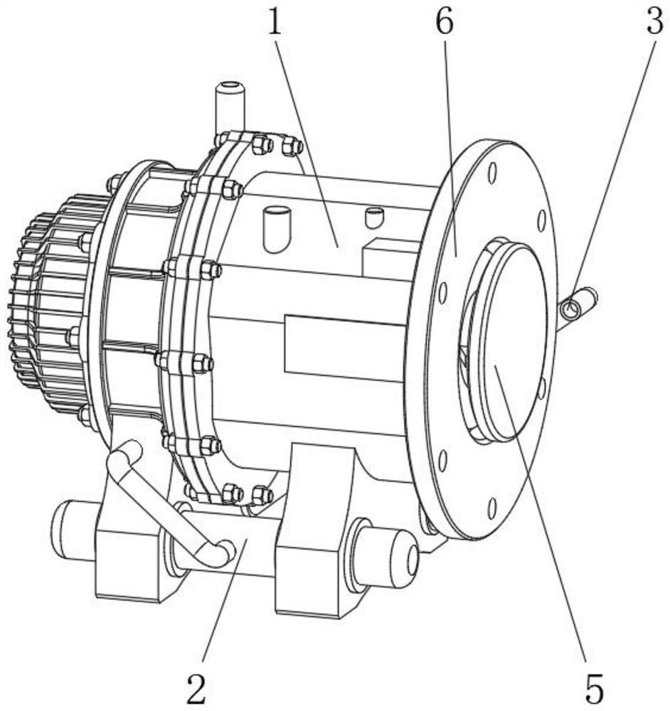
[0022] see Figure 1-4 , an air compressor for an automobile braking system, comprising an air compressor main body 1, an air storage tank 2 is fixedly installed at the bottom of the air compressor main body 1, and the inside of the air compressor main body 1 is connected to the air storage tank through a connecting pipe 3 The interior of the gas tank body 2 is connected, and the inner cavity of the gas storage tank body 2 is respectively connected with the br...


PUM


Abstract

The invention relates to the technical field of automobile braking equipment, and discloses an air compressor for an automobile braking system. The air compressor comprises an air compressor main body, an air storage tank body is fixedly mounted at the bottom end of the air compressor main body, the interior of the air compressor main body communicates with the interior of the air storage tank body through a connecting pipeline, an inner cavity of the air storage tank body communicates with the braking system and a parking system on an electric automobile through pipelines, a friction plate I is fixedly installed at one end of an output shaft of the air compressor main body, and an installation disc body is arranged on the right side of the outer portion of the air compressor main body. According to the air compressor for the automobile braking system, a balance air bag is arranged on the air storage tank body, so that air pressure in the air storage tank body can be balanced when a motor spindle on the electric automobile stops rotating, then the phenomenon that the air pressure in the air storage tank body changes due to expansion caused by heat and contraction caused by cold can be effectively avoided, and further, a sufficient and stable braking pressure source is provided for the braking system and the parking system on the electric automobile.

Description

technical field [0001] The invention relates to the technical field of automobile braking equipment, in particular to an air compressor for an automobile braking system. Background technique [0002] As a major trend in the development of the automotive industry, electric vehicles have broad development prospects because their impact on the environment is much smaller than traditional fuel vehicles. An air compressor is required to provide sufficient brake pressure for its brakes. [0003] For the setting of the air compressor on the existing electric vehicle, its power shaft is connected with the motor shaft on the electric vehicle. As long as the motor on the electric vehicle starts to work, it will drive the air compressor to work together, which increases The working load of the motor on the electric vehicle is reduced, and a pressure control valve needs to be installed on the air storage tank to adjust the pressure in it, which in turn causes a loss of motor power outp...

Claims


Application Information

Patent Timeline
Patent Type & Authority Applications(China)
IPC IPC(8): F04B35/04F04B41/02F04B49/02F16D25/04F17C13/12
CPCF04B35/04F04B41/02F04B49/022F16D25/048F17C13/123
Inventor 胡东风
Owner 胡东风
Learn More