
Novel hard alloy inner-cooling deep hole twist drill

A cemented carbide and twist drill technology, which is applied in twist drills, drilling/drilling equipment, drill repairing, etc., can solve the problems that chips cannot be taken away quickly, broken, easy to generate vibration, etc.

Pending Publication Date: 2021-05-11
SUZHOU AHNO PRECISION CUTTING TECH CO LTD
View PDF0 Cites 0 Cited by
  • Summary
  • Abstract
  • Description
  • Claims
  • Application Information

AI Technical Summary

Problems solved by technology

Compared with ordinary twist drilling, deep hole machining has a deeper cutting hole and a longer chip removal distance. When the coolant pressure is insufficient, the chips cannot quickly take away the heat generated during the cutting process, resulting in the cutting edge of the drill bit due to high temperature. It will cause plastic deformation and wear, and it is also prone to chip blocking, resulting in chip blocking or drill chipping, and even the phenomenon that the drill bit is broken due to too much torque.
[0004] In addition, due to the large overhang of the deep-hole twist drill and the poor rigidity of the process system, vibrations are easily generated during the drilling process, resulting in poor cutting positioning accuracy and easy deflection of the drill hole. In severe cases, the drill bit may even break and affect Machining accuracy and production efficiency
Therefore, it is necessary to design a new type of cemented carbide internal cooling deep hole twist drill to solve the problem of high cutting temperature, poor chip removal, poor tool rigidity, easy vibration and deflection during drilling, resulting in tool wear, cutting edge chipping, etc. Drill pipe breakage and other problems

Method used


Image

  • Novel hard alloy inner-cooling deep hole twist drill
  • Novel hard alloy inner-cooling deep hole twist drill
  • Novel hard alloy inner-cooling deep hole twist drill

Examples


Embodiment Construction

[0032] The embodiments of the present invention are described in detail below, so that the advantages and features of the present invention can be more easily understood by those skilled in the art, so as to define the protection scope of the present invention more clearly.

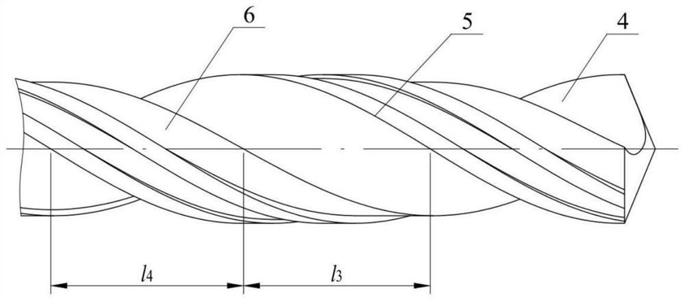
[0033] like Figure 1-6 As shown, a new hard alloy internal cooling deep hole twist drill includes a cylindrical handle 1 and a cutter body arranged on the cylindrical handle 1. The cutter body includes a cutting edge 2 and is used to connect the cylindrical handle 1 and the The transition neck 3 of the cutting edge 2; the material of the cutter body is 10% cobalt, and the fracture toughness is K IC Higher submicron carbide internally cooled bar stock; diameter d of cylindrical shank 1 1 Greater than or equal to the diameter d of the cutting edge portion 2 2 The minimum even value of the cutting edge part 2 diameter d 2 3mm to 10mm.

[0034] like figure 2 As shown, due to the long overhang of the de...


PUM


Abstract

The invention discloses a novel hard alloy inner-cooling deep hole twist drill. The novel hard alloy inner-cooling deep hole twist drill comprises a cylindrical handle part and a cutter body arranged on the cylindrical handle part, the cutter body comprises a cutting edge part and a transition neck part connected with the cylindrical handle part and the cutting edge part, chip grooves are formed in the cutting edge part, and the cutting edge part adopts the front inverted cone and rear parallel core thickness design. The chip grooves intersect with the solid part of the cutter body to form two auxiliary cutting edges and two edge flaps, the cutting edge part is provided with two rear cutter faces and two chip containing grooves, the two rear cutter faces intersect to form a chisel edge, the two rear cutter faces intersect with the two chip grooves to form two main cutting edges, the two rear cutter faces intersect with the two chip containing grooves to form two inner cutting edges, and the cutting rake angles of the main cutting edges and the inner cutting edges are different. According to the novel hard alloy inner-cooling deep hole twist drill, the problems that the deep hole machining cutting temperature is high, chip removal is not smooth, the cutter rigidity is poor, vibration deflection is prone to happening during drilling, consequently, the cutter is worn, the cutting edge is broken, and a drill rod is broken are solved.

Description

technical field [0001] The invention belongs to the technical field of deep hole twist drills, and in particular relates to a novel cemented carbide internal cooling deep hole twist drill. Background technique [0002] In metal cutting processing, the hole drilling process accounts for about 40% to 50% of the total cutting processing, especially in the aerospace and automobile manufacturing industries, and the production of drill bits accounts for about 60% of the total output of cutting tools. . Among them, the twist drill is one of the most common hole drilling tools, and it is also one of the tools with the largest loss in mechanical cutting, while the deep hole twist drill is used for the ratio of drilling depth to drilling diameter not less than 12 deep hole processing. [0003] Hole drilling is a processing method in a semi-closed state. Due to its semi-closed nature, the friction between the tool and the workpiece is large and the cutting temperature is high during ...

Claims


Application Information

Patent Timeline
IPC IPC(8): B23B51/02B23B51/06
CPCB23B51/02B23B51/06B23B2251/408
Inventor 沈钰于道海沈秋波
Owner SUZHOU AHNO PRECISION CUTTING TECH CO LTD
Learn More