
Manufacturing method of pressure release valve mounting hole in battery box

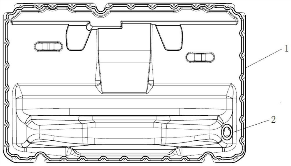
A manufacturing method and battery box technology, which is applied in the field of new energy vehicle battery box manufacturing, can solve problems affecting the assembly of pressure relief valves, increase the scrapping rate of pressure relief valves, and deformation of pressure relief valve installation holes, so as to eliminate burrs and reduce scrapping rate, damage avoidance

Active Publication Date: 2021-05-11
上海赛科利汽车模具技术应用有限公司
View PDF7 Cites 2 Cited by
  • Summary
  • Abstract
  • Description
  • Claims
  • Application Information

AI Technical Summary

Problems solved by technology

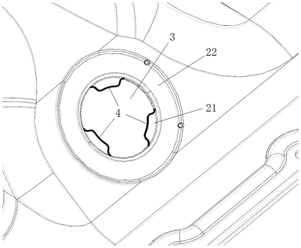
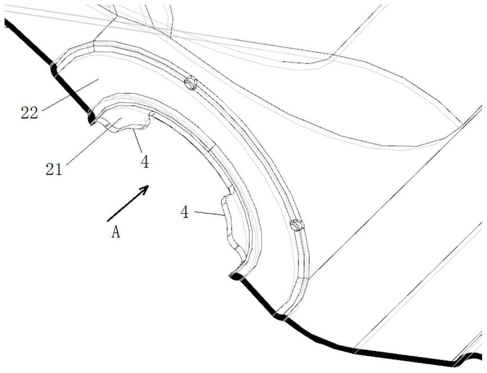
There will be burrs in the stamping process of the aluminum product battery box. Since the pressure relief valve installation hole is punched out, burrs will be generated on the edge of the pressure relief valve installation hole. These burrs will cause the pressure relief valve installation hole The scrap rate of the pressure relief valve increases during assembly, and punching at the same time will cause a certain deformation at the installation hole of the pressure relief valve, which will affect the assembly of the pressure relief valve

Method used


Image

  • Manufacturing method of pressure release valve mounting hole in battery box
  • Manufacturing method of pressure release valve mounting hole in battery box
  • Manufacturing method of pressure release valve mounting hole in battery box

Examples


Embodiment Construction

[0031] The implementation of the present invention will be illustrated by specific specific examples below, and those skilled in the art can easily understand other advantages and effects of the present invention from the contents disclosed in this specification.

[0032] It should be noted that the structures, proportions, sizes, etc. drawn in the drawings of this specification are only used to match the content disclosed in the specification, for those who are familiar with this technology to understand and read, and are not used to limit the conditions for the implementation of the present invention. Therefore, there is no technical substantive meaning, and any modification of structure, change of proportional relationship or adjustment of size shall still fall within the scope of the disclosure of the present invention without affecting the functions and objectives of the present invention. within the scope of technical content. At the same time, terms such as "upper", "lo...


PUM

PropertyMeasurementUnit
Hardnessaaaaaaaaaa

Abstract

The invention relates to a manufacturing method of a pressure release valve mounting hole in a battery box. The manufacturing method comprises the following working procedures of a material falling working procedure, a stretching working procedure, a punching working procedure and a trimming and shaping working procedure. The battery box with a stepped surface structure is obtained through the material falling working procedure and the stretching working procedure, the pressure release valve mounting hole is punched in a first stepped panel of the stepped surface structure through the punching working procedure, and a reverse R-angle insert is manufactured through the trimming and shaping working procedure. The reverse R-angle insert is used for conducting shaping treatment on the pressure release valve mounting hole in the direction opposite to the punching direction of the pressure release valve mounting hole, so that the flatness of the first stepped panel is adjusted, the height difference between the first stepped panel and a second step panel is adjusted, and it is guaranteed that the pressure release valve mounting process requirements are met. A burr shaping protrusion of the reverse R-angle insert is pressed to abut against the burr area on the edge of the pressure release valve mounting hole, burrs are eliminated, damage caused by the burrs during pressure release valve mounting is avoided, and the rejection rate of pressure release valve mounting is reduced.

Description

technical field [0001] The invention relates to the field of manufacturing new energy vehicle battery boxes, in particular to a method for manufacturing a pressure relief valve mounting hole on a battery box. Background technique [0002] With the development of production technology and the improvement of environmental protection awareness, the emergence of new energy vehicles has become an inevitable development of the times. . According to different vehicle fuels, new energy vehicles can be divided into: pure electric vehicles, hybrid vehicles, fuel cell electric vehicles, hydrogen engine vehicles, etc. From the perspective of the development of global new energy vehicles, their power sources mainly include lithium-ion batteries, nickel-metal hydride batteries, fuel cells, lead-acid batteries, super capacitor batteries, etc. [0003] Hybrid vehicles usually refer to gasoline-electric hybrid vehicles, which use traditional internal combustion engines and electric motors ...

Claims


Application Information

Patent Timeline
IPC IPC(8): B21D35/00B21D28/26B21D19/00
CPCB21D35/001B21D35/002B21D28/26B21D19/005Y02E60/10
Inventor 魏德礼潘敏慧
Owner 上海赛科利汽车模具技术应用有限公司
Learn More