Laser-microwave composite deicing system and method

A laser and microwave technology, applied in the field of laser applications, can solve problems such as normal operation of high-voltage wires affecting blade life, icing of fan blades and high-voltage wires, safety hazards of units and on-site personnel, etc. fast effect

Pending Publication Date: 2021-05-07
宝宇(武汉)激光技术有限公司
View PDF0 Cites 3 Cited by
  • Summary
  • Abstract
  • Description
  • Claims
  • Application Information

AI Technical Summary

Problems solved by technology

Due to the high altitude and low temperature, the fan blades and high-voltage wires in these areas are prone to icing in winter; when the blades or high-voltage wires freeze, it will not only increase the load, affect the life of the blades or the normal operation of the high-voltage wires, but also When the icing is severe, there will be problems that the unit has to be disconnected from the grid or the high-voltage wire is broken, which greatly reduces the utilization rate of the unit in low temperature areas for many years
In addition, after the blades or high-voltage wires freeze, as the temperature rises, the ice cubes will fall off, which will not only cause great safety hazards to the unit and on-site personnel, but also cause serious damage to the blades or high-voltage wires. Or high-voltage wires are broken, which threatens the safety of personnel in wind farms or substations; at the same time, when the blades are covered with ice, the efficiency of the unit will also be reduced, resulting in a loss of 1%-10% of the annual power generation. Regional annual power loss may even reach 20%-50%
[0003] At present, there are many ways of deicing wind turbine blades, such as: mechanical deicing, thermal deicing, chemical spraying deicing, ultrasonic vibration deicing, electromagnetic pulse deicing, etc., but these are based on heat, electricity, manpower, etc. The passive deicing method is not only time-consuming, labor-intensive, energy-consuming, inefficient, but also expensive, and cannot fundamentally solve the above problems

Method used


Image

  • Laser-microwave composite deicing system and method
  • Laser-microwave composite deicing system and method

Examples


Embodiment Construction

[0048]In order to make the techniques, creative characteristics, objective and efficacy of the present invention, which will be further illustrated in connection with the accompanying drawings and specific embodiments.

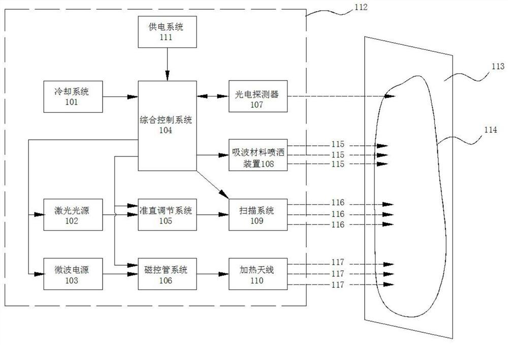
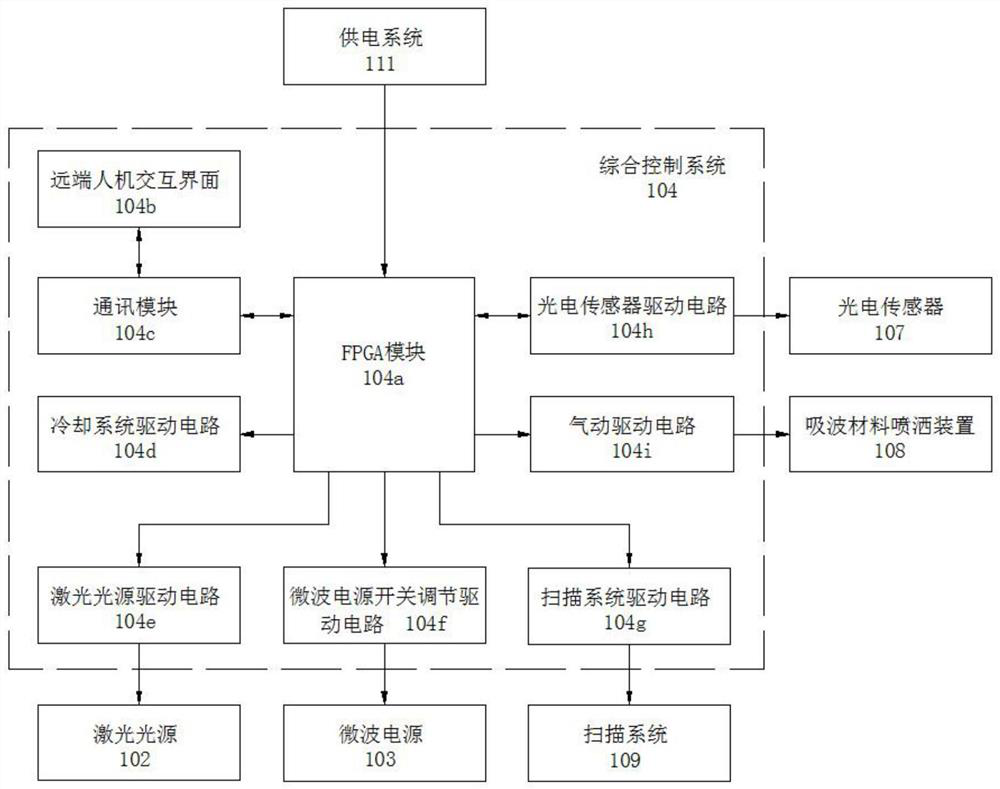
[0049]Seefigure 1 As shown, the laser-microwave composite de-ice system provided by the present invention includes a cooling system 101, a laser light source 102, a microwave power source 103, a composite control system 104, a collimator adjustment system 105, a magnetron system 106, and a photoelectric sensor 107. , The absorbing material spraying device 108, the scanning system 109, and the heating antenna 110, the integrated control system 105 respectively corresponds to the cooling system 101, a laser light source 102, a microwave power source 103, a collimation adjustment system 106, a magnetron system 106, a photoelectric sensor 107, The absorbing material spraying device 108 and the scanning system 109 are electrically connected;

[0050]Wherein, the cooling system...


PUM


Abstract

The invention discloses a laser-microwave composite deicing system and method. The deicing system comprises a comprehensive control system, and a cooling system, a laser light source, a microwave power supply, a collimation adjusting system, a magnetron system, a photoelectric sensor, a wave-absorbing material spraying device, a scanning system and a power supply system which are electrically connected with the comprehensive control system respectively, and the deicing system further comprises a heating antenna which is connected with the magnetron system, and a movable carrier system which is used for bearing all subsystems. The deicing method mainly comprises the following steps: firstly, acting on an ice layer by adopting a pulse laser beam to form water and porous gaps on the surface of the ice layer; then spraying a wave-absorbing material to the surface of the ice layer and gaps of the ice layer; and finally, heating the ice layer remotely through a large-breadth continuous laser beam and microwaves, achieving the purpose of rapidly removing ice covering the surface of a target object in a large area. The system and the method have the advantages of being flexible in application, wide in application range, low in energy consumption, free of pollution, high in working efficiency, high in performance ratio and free of damage to base materials.

Description

Technical field[0001]The present invention relates to the field of laser applications, and in particular, to a laser-microwave composite degenerative system and method.Background technique[0002]Most of the wind power plants and high voltage wires are located in high-level cold and wind energy resources in high altitude and wind energy resources. Due to the high altitude and low temperature, the fan blades and high voltage wires are extremely easy to have ice in winter; while the blades or high-voltage wires will not only cause the load to increase, affect the long life of the leaves or high voltage wires, and When the icing is serious, the unit has to go off the network to shut down or the high-voltage wire is broken, so that the utilization rate of units in a low temperature area is greatly reduced. In addition, after the blade or high voltage wire is frozen, the ice will fall off, not only cause a lot of safety on the unit and the on-site person, but also when the leaves or high-v...

Claims


Application Information

Patent Timeline
Patent Type & Authority Applications(China)
IPC IPC(8): H02G7/16H02G1/02
CPCH02G1/02H02G7/16
Inventor 湛欢李震刘梅丁铮陈建王亦军汤磊辛志文陈文忠
Owner 宝宇(武汉)激光技术有限公司
Why Eureka
Try Eureka