Self-centering anti-vibration clamp for gear grinding machining of thin radial plate gear part and clamping method

A self-centering and spoke technology, applied in gear tooth manufacturing devices, manufacturing tools, components with teeth, etc., can solve the problem of failure to meet design requirements, difficulty in clamping and aligning parts, and affecting the safety and use of parts. life and other issues, to achieve the effect of improving the processing quality

Active Publication Date: 2021-05-07
ZHONGNAN TRANSMISSION MACHINERY FACTORY CHANGSHAAVIATION IND
View PDF6 Cites 0 Cited by
  • Summary
  • Abstract
  • Description
  • Claims
  • Application Information

AI Technical Summary

Problems solved by technology

[0003] The existing gear grinding process mainly adopts a clamp structure with one clamp and one top, and the outer circle of the parts For positioning, the fixture is supported by the end face of the tooth on the radial plate, and the end face of the lower tooth of the radial plate is pressed and fixed; the lower end of the fixture is fixed to the machine tool, and the upper end of the fixture is supported by the top of the machine tool. Using this type of fixture for the gear grinding process, it is difficult to align the parts. Due to the small tooth width during processing, the teeth are prone to chatter. After processing, the tooth surface quality such as tooth shape and direction is poor, which cannot meet the design requirements, which in turn affects the dynamic unbalance of the parts, thus affecting the safety and service life of the parts.

Method used


Image

  • Self-centering anti-vibration clamp for gear grinding machining of thin radial plate gear part and clamping method
  • Self-centering anti-vibration clamp for gear grinding machining of thin radial plate gear part and clamping method
  • Self-centering anti-vibration clamp for gear grinding machining of thin radial plate gear part and clamping method

Examples


Embodiment 1

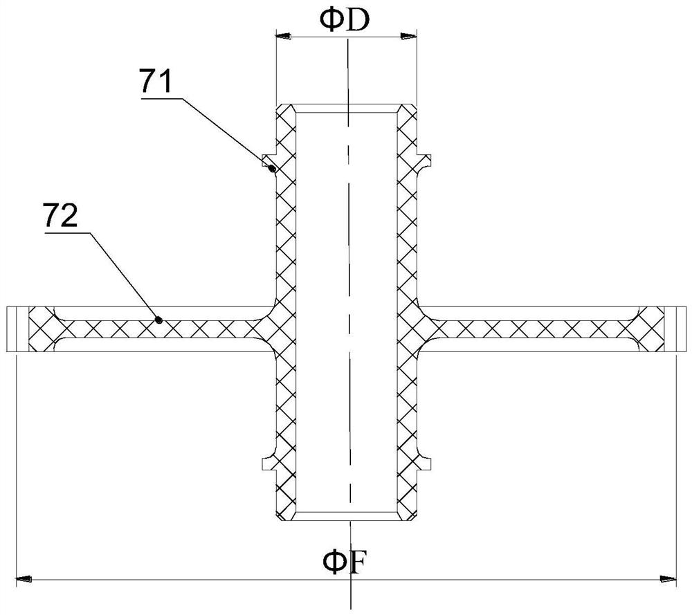
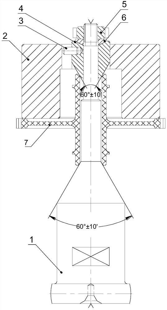
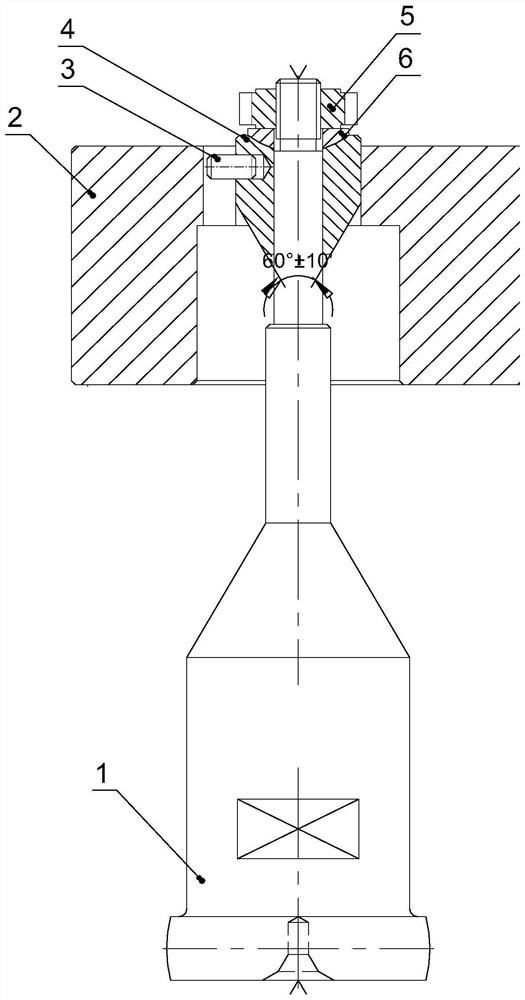
[0035] Such as Figures 1 to 10 As shown, a self-centering anti-vibration fixture for the grinding of thin-web gear parts according to the present invention includes a mandrel 1, a tapered sleeve 4 and a nut 5, and the mandrel 1 includes spherical columns 11 from bottom to top , Conical frustum 12, center column 13 and external thread 14, nut 5 is matched with external thread 14, taper sleeve 4 is set outside the center column 13; thin spoke plate gear part 7 includes through-hole shaft 71 and circumferentially arranged on the through-hole The thin-walled radial plate 72 on the outer wall of the hole shaft 71, the inner hole of the through hole shaft 71 passes through the center column 13 and the lower end of the inner hole is matched with the cone 12; the taper sleeve 4 is located between the through hole shaft 71 and the nut 5 and the lower end of the taper sleeve 4 Cooperate with the upper end of the inner hole of the through-hole shaft 71, tighten the nut 5 to fix the thro...


PUM


Abstract

The invention discloses a self-centering anti-vibration clamp for gear grinding processing of a thin radial plate gear part. The clamp comprises a core rod, a taper sleeve and a nut. The core rod sequentially comprises a spherical column, a frustum, a central column and an external thread from bottom to top. The nut is matched with the external thread. The taper sleeve sleeves the central column. The thin radial plate gear part comprises a through hole shaft and a thin radial part gear, wherein the lower end of an inner hole of the through hole shaft is matched with the frustum. The taper sleeve is located between the through hole shaft and the nut, the lower end of the taper sleeve is matched with the upper end of an inner hole of the through hole shaft, and the nut is screwed to fix the through hole shaft between the taper sleeve and the frustum. A bottom center hole and a top center hole are formed in the lower end and the upper end of the core rod respectively, the bottom center hole is used for being matched with a base center of a machine tool, and the top center hole is used for being matched with an upper center of the machine tool. According to the device, the part can be quickly aligned, and vibration is effectively prevented when the part is machined.

Description

technical field [0001] The invention relates to the field of gear grinding fixtures, in particular to a self-centering anti-vibration fixture and a clamping method for grinding teeth of thin web gear parts. Background technique [0002] The design of aero-engine parts is gradually developing in the direction of light weight, heavy load and high speed, which has high production requirements and makes processing difficult. High-performance engine gears have the characteristics of high power-to-weight ratio, high strength, high speed, and high dynamic balance accuracy requirements. Thin web structure is generally used. High standard. Grinding process [0003] The existing gear grinding process mainly adopts a clamp structure with one clamp and one top, and the outer circle of the parts For positioning, the fixture is supported by the end face of the tooth on the radial plate, and the end face of the lower tooth of the radial plate is pressed and fixed; the lower end of the ...

Claims


Application Information

Patent Timeline
IPC IPC(8): B23F23/06B23F5/02
CPCB23F23/06B23F5/02
Inventor 罗平华陶琪黄光肖涛瞿志军陈龙张力张赞龙
Owner ZHONGNAN TRANSMISSION MACHINERY FACTORY CHANGSHAAVIATION IND
Why Eureka
Try Eureka