


Quick Research
Generate reliable direction feasibility study reports for your R&D in just a few steps.

Technical Q&A
Discover and master advanced knowledge NOW. Basics, ideas, possibilities, all at once.

Find Solutions
As an expert in R&D theories, this can generate solutions to your technical problems instantly.

Evaluate Feasibility
Analyze your overall solution with one click, know your potential R&D risks in advance.

Monitor Landscape
Get weekly tech updates, stay abreast of the latest tech innovations and key insights.
Wavefront aberration measurement system, associated visual perception learning training system and method
A wavefront aberration and measurement system technology, applied in the field of aberration measurement system and ophthalmology optics, can solve the problem of low measurement accuracy of large refractive error, limited ability to measure low-order aberrations, and failure to measure high-order aberrations of the human eye. Aberration and other problems, to achieve high maintenance costs, improve instrument performance, and avoid measurement errors
- Summary
- Abstract
- Description
- Claims
- Application Information
AI Technical Summary
Problems solved by technology
Method used
Image

Examples
Embodiment 1
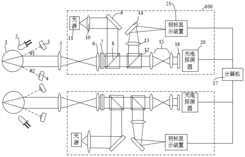
[0071] Embodiment 1 of the present invention provides a wavefront aberration measurement system 100 . The system is provided with a left eye and a right eye path. The operation of the system is described below.
[0072] Step 1 Three-dimensional positioning of binocular pupils
[0073] When working, first perform the three-dimensional positioning of the binocular pupils. For the convenience of description, the figure 1 The left-hand work shown is described. Use infrared light-emitting diode 2 to illuminate the pupil of the left eye 1 to be measured, the first pupil camera 3 and the second pupil camera 4, the first pupil camera 3 and the second pupil camera 4 form a pupil camera pair, and the pupil camera pair (3, 4) pairs It is fixed at a certain interval, and its axis keeps the same angle with the optical axis, that is, θ1=θ2.
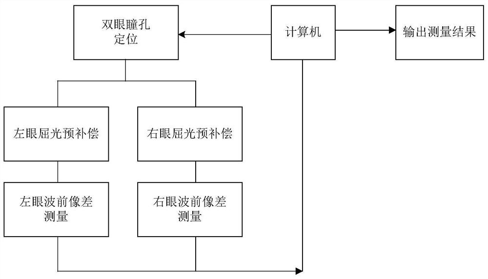
[0074] image 3 A block diagram schematically shows the working relationship between the computer 17 and other devices. According to the imag...
Embodiment 2
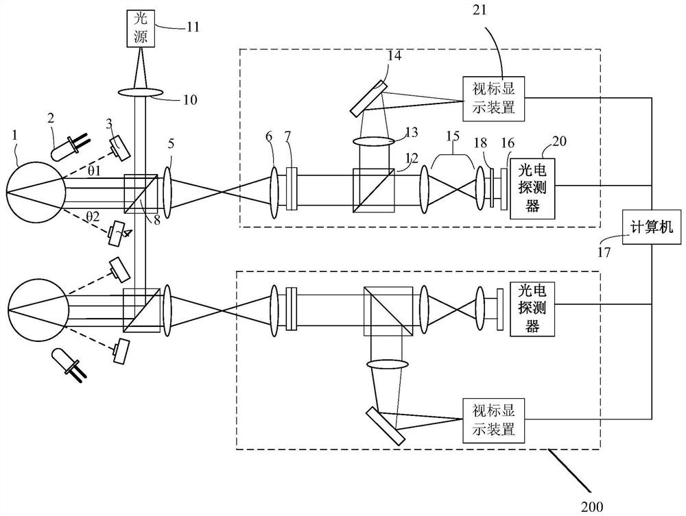
[0083] The same or similar components use the same reference numerals as in Embodiment 1. Embodiment 2 of the present disclosure provides another wavefront aberration measurement system 200 . The system is provided with a left eye and a right eye path. Such as figure 2 shown.
[0084] Step 1 Three-dimensional positioning of binocular pupils
[0085] When the wavefront aberration measurement system 200 is started and started to work, the three-dimensional positioning of the binocular pupils is first performed. For the convenience of description, the figure 2 The left-hand work shown is described. Use the infrared light-emitting diode 2 to illuminate the pupil of the measured human eye 1 (left eye), the first pupil camera 3 and the second pupil camera 4 are fixed at a certain interval, and their axes keep the same angle with the optical axis, that is, θ1=θ2 . According to the images collected by the first pupil camera 3 and the second pupil camera 4, the computer 17 o...
Embodiment 3
[0092] The disclosure further provides application embodiments. As described above, the present disclosure provides a wavefront aberration measurement system. The wavefront aberration measurement system can provide more accurate wavefront aberration measurement. Since the system is a precision instrument, the cost is relatively high. In order to expand the application scene, the present invention further provides a new application mode.
[0093] Embodiment 3 provides a kind of visual perception learning training method, comprises the steps:
[0094] Step 1 Use the wavefront aberration measurement system of the present invention to obtain the wavefront aberration parameters of the subject;
[0095] Step 2 provides the subject with a separate visual function correction training device, which includes an aberration correction device and a visual function training device. Further, the visual function correction training device does not configure an aberration measurement system,...
PUM
 Abstract
Description
Claims
Application Information
 - R&D Engineer
- R&D Manager
- IP Professional
- Industry Leading Data Capabilities
- Powerful AI technology
- Patent DNA Extraction
Browse by: Latest US Patents, China's latest patents, Technical Efficacy Thesaurus, Application Domain, Technology Topic, Popular Technical Reports.
© 2024 PatSnap. All rights reserved.Legal|Privacy policy|Modern Slavery Act Transparency Statement|Sitemap|About US| Contact US: help@patsnap.com