Eureka AIR delivers breakthrough ideas for toughest innovation challenges, trusted by R&D personnel around the world.

Self-propelled concrete curing device for water conservancy construction

A concrete and self-propelled technology, applied in spraying devices, spraying devices with movable outlets, infrastructure engineering, etc., can solve the problems of limited spraying range and low efficiency of maintenance operations

Inactive Publication Date: 2021-04-30
吴世萍
View PDF0 Cites 0 Cited by
  • Summary
  • Abstract
  • Description
  • Claims
  • Application Information

AI Technical Summary

Problems solved by technology

[0003] The existing concrete maintenance device for water conservancy construction includes a box body, a box door, a first powerful magnet, a second powerful magnet, universal wheels and a water heater. On one side of the box body, the box door moves with the box body through a hinge. There are sealing strips around the inner surface of the box door, universal wheels are fixedly connected to the bottom of the box, and water heaters are fixedly connected to the top of the box. Although this device can be used for watering and curing of concrete, the watering during the curing process The spray range is relatively limited, resulting in low maintenance operation efficiency. Therefore, a self-propelled concrete maintenance device for water conservancy construction is now provided to solve the above technical problems

Method used


Image

  • Self-propelled concrete curing device for water conservancy construction
  • Self-propelled concrete curing device for water conservancy construction
  • Self-propelled concrete curing device for water conservancy construction

Examples


Embodiment 1

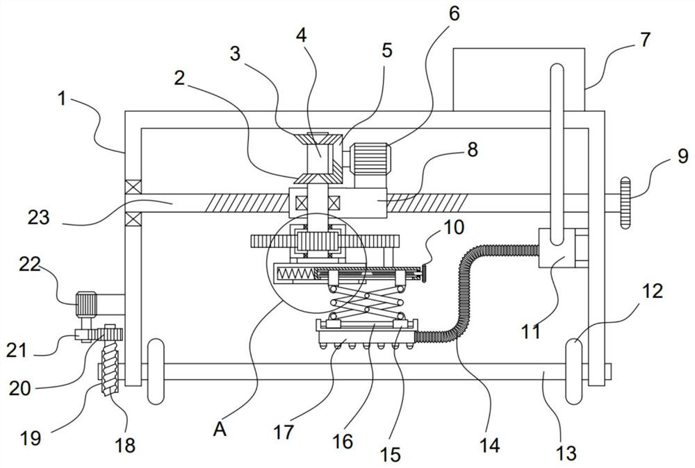
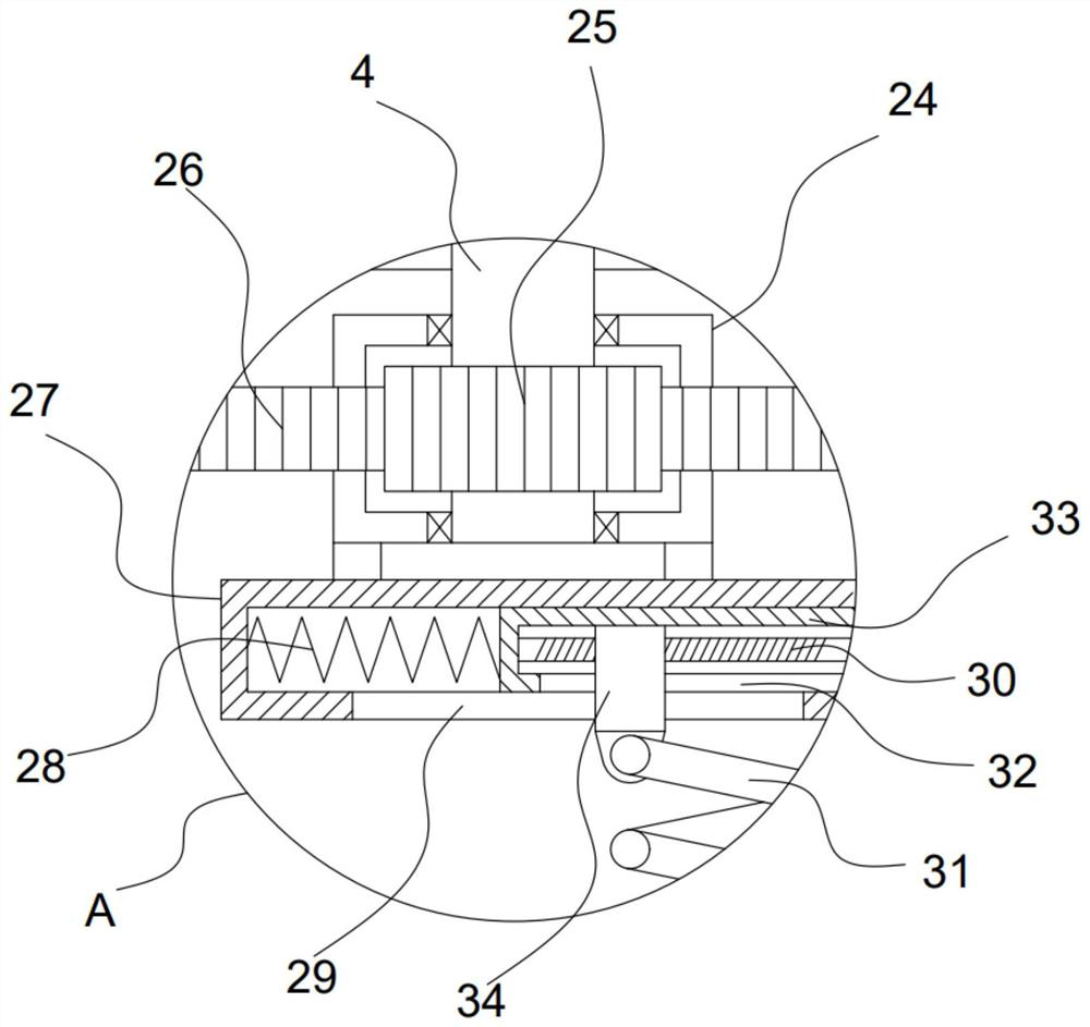
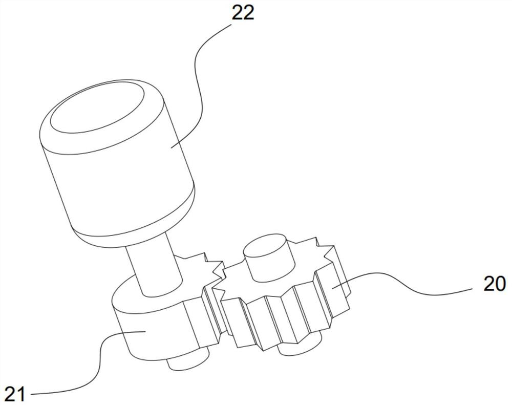
[0021] see Figure 1-3 , a self-propelled concrete maintenance device for water conservancy construction, comprising a walking frame 1, a transmission shaft 13 is installed in rotation on the bottom of the walking frame 1, a traveling wheel 12 is sleeved and fixed on the transmission shaft 13, and a horizontal adjustment is arranged on the walking frame 1 The horizontal adjustment mechanism is provided with a servo motor 6, and the servo motor 6 is driven and connected with a deflection mechanism. The bottom of the deflection mechanism is fixed with a guide sleeve 27, and a telescopic sleeve 33 is slidably installed in the guide sleeve 27. The bottom of the sleeve 33 is provided with a vertical lifting mechanism, the bottom of the vertical lifting mechanism is fixed with a sprinkler mechanism for spraying water on the concrete, and the driving motor 22 is fixed on the walking frame 1, and the driving motor 22 is connected by a transmission. It is a moving mechanism for driving...

Embodiment 2

[0026] On the basis of Embodiment 1, in addition, the spray mechanism of this device includes the water tank 7 fixed on the top of the walking frame 1 and the delivery pump 11 communicated with the water tank 7, and the outlet end of the delivery pump 11 communicates with a The shower plate 17 that is fixed on the bottom of the vertical lifting mechanism. The inside of the water tank 7 is used to store the clean water to be sprayed, and the delivery pump 11 is set to extract the clean water, and finally spray it downwards from the spray plate 17 to achieve the curing effect on the concrete.

[0027] The vertical lifting mechanism of the device includes two threaded rods 30 that are coaxially fixed in the telescopic sleeve 33 and have opposite screw threads. The ends of the threaded rods 30 are fixed with hand wheels II10. A threaded block 34 is sleeved, the guide sleeve 27 and the telescopic sleeve 33 are provided with a strip hole I29 and a strip hole II32 for the threaded bl...


PUM


Abstract

The invention discloses a self-propelled concrete curing device for water conservancy construction, and relates to the technical field of water conservancy construction. The self-propelled concrete curing device comprises a walking frame, wherein a transmission shaft is rotationally installed at the bottom of the walking frame, walking wheels are fixed to the transmission shaft in a sleeving mode, a vertical lifting mechanism is arranged at the bottom of a telescopic sleeve, a spraying mechanism used for spraying water to concrete is fixed to the bottom of the vertical lifting mechanism, and a driving motor is fixed to the walking frame. According to the self-propelled concrete curing device, the telescopic sleeve can be driven through an arranged deflection mechanism, the telescopic sleeve drives a spraying disc in the spraying mechanism to achieve automatic clockwise and anticlockwise swing and meanwhile achieve reciprocating sliding relative to a guide sleeve, and at the moment, water sprayed out of the spraying disc can be completely sprayed to the surface of the concrete to be cured; and meanwhile, an arranged moving mechanism can drive the walking wheels to rotate in a stepping mode, intermittent movement of the spraying disc is achieved, and the effect that the water is fully sprayed to the concrete in different areas section by section for curing is achieved.

Description

technical field [0001] The invention relates to the technical field of water conservancy construction, in particular to a self-propelled concrete maintenance device for water conservancy construction. Background technique [0002] Water conservancy projects are projects built to control and allocate natural surface water and groundwater to achieve the purpose of eliminating harm and rejuvenating profits. Also known as water engineering. Water is an indispensable precious resource for human production and life, but its natural state does not fully meet human needs. Only by building water conservancy projects can we control water flow, prevent floods, and regulate and distribute water to meet the needs of people's life and production for water resources. Water conservancy projects need to build different types of hydraulic structures such as dams, dikes, spillways, sluices, water inlets, channels, canals, rafts, and fishways to achieve their goals. [0003] The existing con...

Claims


Application Information

Patent Timeline
Patent Type & Authority Applications(China)
IPC IPC(8): E02D15/00E04G21/24B05B3/14B05B3/18
CPCB05B3/14B05B3/18E02D15/00E04G21/246
Inventor 吴世萍
Owner 吴世萍
Why Eureka
Eureka Blog
Learn More