Cam driven pin-pricking type rubber cutting machine

A technology for driving needles and rubber tapping machines, applied in forestry, application, agriculture, etc., can solve the problems of large bark cutting consumption, difficult operation, complex structure, etc., and achieve the effect of simple structure, convenient operation and large driving force

Pending Publication Date: 2019-10-15
HAINAN ZHONG XIANG TECH CO LTD
View PDF0 Cites 2 Cited by
  • Summary
  • Abstract
  • Description
  • Claims
  • Application Information

AI Technical Summary

Problems solved by technology

However, this method of tapping rubber is difficult to operate, and there is a large amount of cutting and consumption of bark, which leads to a reduction in the number of tapped rubber trees.
At present, there are needle-punched rubber harvesters, which use needles to pierce the rubber tree and pull them out. However, because needle-punched rubber harvesters need to realize the insertion, pull-out and moving position of the needles, it is necessary to move along the direction of the guide rail. It also needs to move along the radial direction of the rubber tree, which leads to the need for multiple motors to drive the needle-punch rubber harvester, and the structure is complicated

Method used


Image

  • Cam driven pin-pricking type rubber cutting machine
  • Cam driven pin-pricking type rubber cutting machine
  • Cam driven pin-pricking type rubber cutting machine

Examples


Embodiment 1

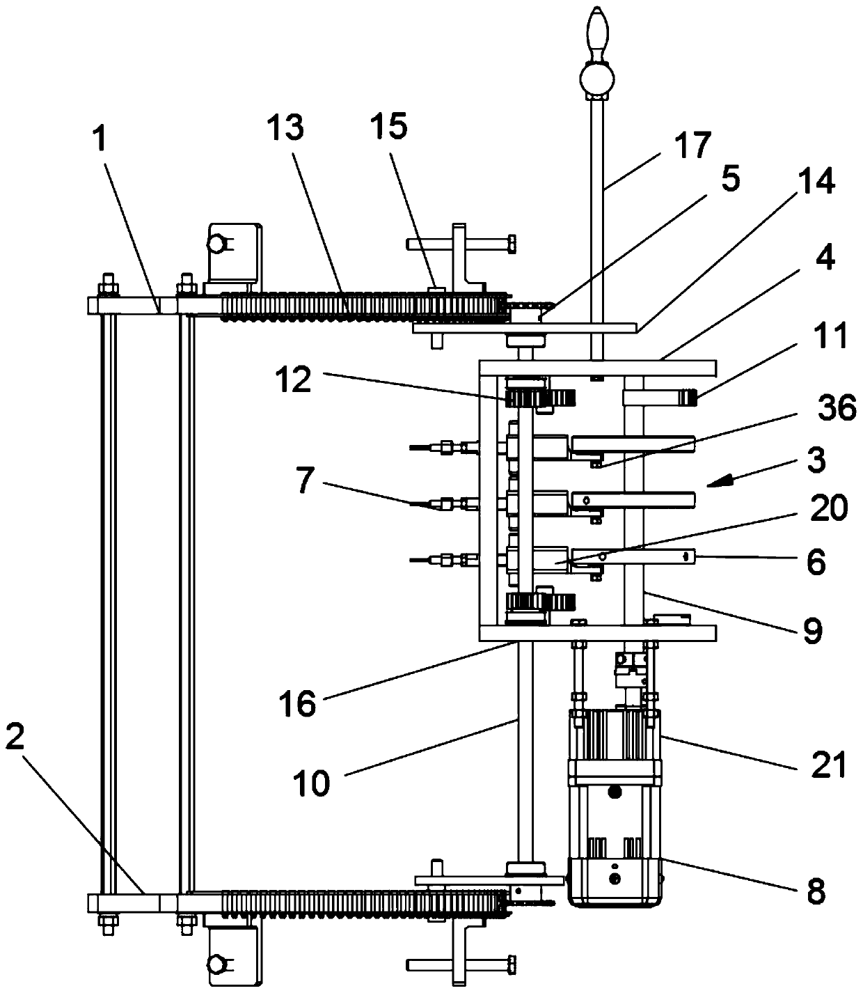
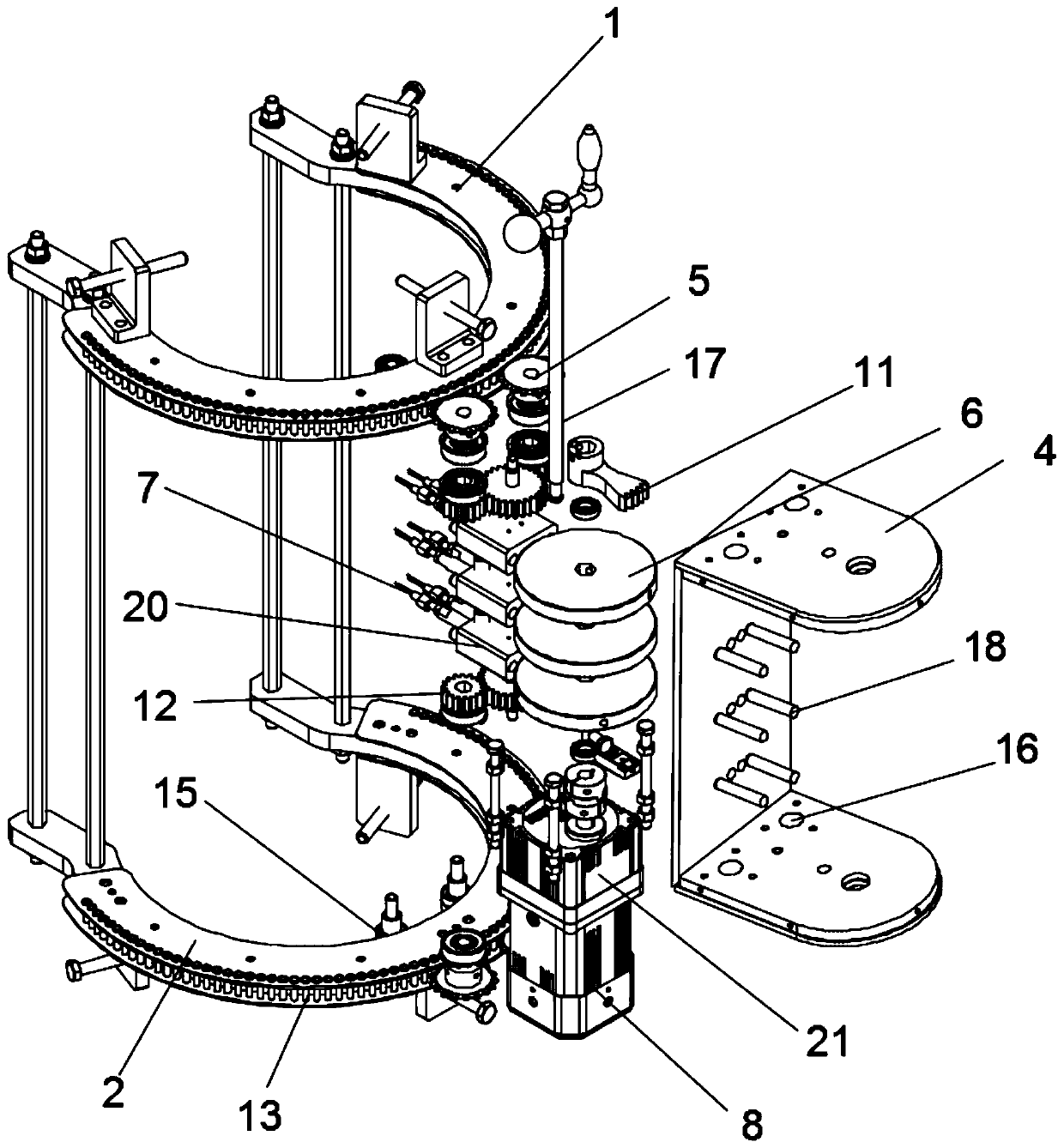
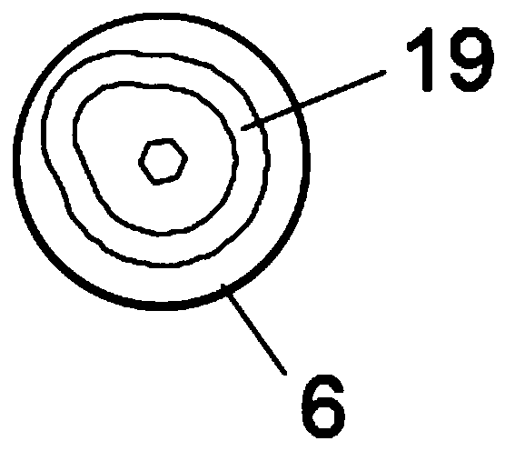
[0024] see Figures 1 to 3 , a cam-driven needle-punched rubber tapping machine, comprising an upper track 1, a lower track 2 and a moving assembly 3, the upper track 1 and the lower track 2 are fixed on a rubber tree, and the moving assembly 3 includes a moving frame 4, a driving wheel 5 , cam 6, needle 7 and motor 8, described moving frame 4 is slidingly connected with described needle 7, and described cam 6 is connected with described moving frame 4 through first rotating shaft 9 rotation, and described needle 7 is on described cam 6 Driven to reciprocate, the motor 8 drives the first rotating shaft 9 to rotate, and the upper and lower ends of the moving frame 4 are respectively provided with the driving wheels that drive the moving assembly 3 to move along the upper track 1 and the lower track 2 5. The driving wheel 5 is rotationally connected with the moving frame 4 through the second rotating shaft 10, the first rotating shaft 9 is provided with sector teeth 11, and the ...

Embodiment 2

[0032] see Figures 4 to 5 , The difference between this embodiment and Embodiment 1 is that the needle 7 includes a sleeve 22, a coil spring 23, a stop bar 24 and a needle bar 25 with a tip, and the needle bar 25 and the sleeve 22 slide connection, the sleeve 22 is provided with the coil spring 23, one end of the coil spring 23 is connected to the needle bar 25, and the other end is connected to the sleeve 22, and the needle bar 25 is connected to the sleeve 22 One end of the sleeve 22 is provided with a bar groove 26, the inner side wall of the sleeve 22 is provided with a limit tooth groove 13, the limit rod 24 is rotatably connected in the bar groove 26, and one end of the limit rod 24 is set There is a limit tooth block 29 for snapping into the limit tooth groove 13, and the other end is provided with a trigger block 30 protruding from the side surface of the needle bar 25, and the bar groove 26 is provided with a pusher to push the position limit. The block snaps into t...


PUM


Abstract

The invention discloses a cam driven pin-pricking type rubber cutting machine. The rubber cutting machine comprises an upper track, a lower track, a moving assembly, wherein the upper track and the lower track are fixed on a rubber tree; the moving assembly comprises a moving frame, driving wheels, cams, pricking pins and a motor; the moving frame is glidingly connected with the pricking pins, thecams are rotationally connected with the moving frame through a first rotating shaft, the pricking pins perform reciprocating motion under the drive of the cams, the motor drives the first rotating shaft to rotate, the driving wheels driving the moving assembly to move along the upper track and the lower track are arranged at upper and lower ends of the moving frame respectively and are rotationally connected with the moving frame through a second rotating shaft, a fan-shaped tooth is arranged on the first rotating shaft, the second rotating shaft is provided with gears, and the fan-shaped tooth drives the gears. The rubber tree can be pricked by piercing the pins, pulling out the pins and moving positions of the pins with one motor as a power input source.

Description

technical field [0001] The invention relates to the technical field of rubber harvesting, in particular to a cam-driven needle-punched rubber tapping machine. Background technique [0002] The traditional natural rubber tapping method is to cut a rubber line obliquely on the rubber tree, and the rubber from the rubber tree flows out along the inclined line and is finally harvested. However, this method of rubber tapping is difficult to operate, and there is a large amount of cutting and consumption of the bark, which leads to a reduction in the number of times the rubber tree can be tapped. At present, there are needle-punched rubber harvesters, which use needles to pierce the rubber tree and pull them out. However, because needle-punched rubber harvesters need to realize the insertion, pull-out and moving position of the needles, it is necessary to move along the direction of the guide rail. It also needs to move along the radial direction of the rubber tree, resulting in ...

Claims


Application Information

Patent Timeline
Patent Type & Authority Applications(China)
IPC IPC(8): A01G23/10
CPCA01G23/10
Inventor 王任飞李振华张毅超李晓莎张艺郭博睿
Owner HAINAN ZHONG XIANG TECH CO LTD
Why Eureka
Try Eureka