A tobacco shredding machine
A technology of cutting machine and tobacco leaves, which is applied in the directions of tobacco, tobacco processing, application, etc., to achieve the effect of being convenient for cutting tobacco leaves, facilitating cutting, and reducing manual operation.
- Summary
- Abstract
- Description
- Claims
- Application Information
AI Technical Summary
Problems solved by technology
Method used
Image

Examples
Embodiment 1
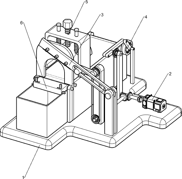
[0037] A tobacco leaf shredder, such as figure 1 As shown, it includes a base 1, a motor 2, a cutting mechanism 3 and an automatic feeding mechanism 4, a motor 2 is installed on the rear right side of the base 1, a cutting mechanism 3 is provided on the front side of the base 1, and the cutting mechanism 3 is connected with the motor 2, An automatic feeding mechanism 4 is arranged on the left side of the base 1 , and the automatic feeding mechanism 4 is connected with the cutting mechanism 3 .
[0038] When the tobacco leaves need to be cut into shreds, first roll the tobacco leaves into the components of the cutting mechanism 3, then start the motor 2, and the motor 2 drives the cutting components of the cutting mechanism 3 to reciprocate up and down. At the same time, the motor 2 drives intermittent The parts of the feeding mechanism operate, and the tobacco leaves move forward intermittently. When the tobacco leaves move forward, the cutting part of the cutting mechanism 3 ...
Embodiment 2
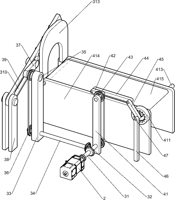
[0040] Specifically, as Figure 1-3 As shown, the cutting mechanism 3 includes a transmission shaft 31, a bevel gear assembly 32, a first support rod 33, a first rotating shaft 34, a second rotating shaft 35, a first belt assembly 36, a rotating rod 37, a second supporting rod 38, and a slide rail. 39. Cutting knives 311, bolts 312, discharge racks 313 and collection boxes 314, a drive shaft 31 is connected to the output shaft of the motor 2, a first support rod 33 is provided at the front of the right side of the base 1, and the lower part of the first support rod 33 A first rotating shaft 34 is rotatably installed, a bevel gear assembly 32 is arranged between the rear side of the first rotating shaft 34 and the left side of the transmission shaft 31, and a second rotating shaft 35 is rotatably arranged on the front side of the upper part of the first support rod 33. The second rotating shaft A first belt assembly 36 is connected between the rear side of 35 and the front side...
Embodiment 3
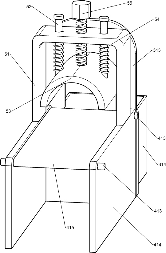
[0045] according to Figure 4-6 As shown, a clamping mechanism 5 is also included. The clamping mechanism 5 includes a fixing frame 51, a fixing rod 52, a clamping plate 53, a first spring 54 and a threaded rod 55. The front side of the cutting table 414 is provided with a fixing frame 51. The rack 51 is located on the rear side of the discharge rack 313 , two fixing rods 52 are slidably installed on the upper part of the fixing frame 51 , the bottom of the fixing rod 52 is connected to the clamping plate 53 , and the top of the clamping plate 53 and the bottom of the fixing frame 51 are connected with a first The spring 54, the first spring 54 is wound around the fixed rod 52, the upper part of the fixed frame 51 is rotatably provided with a threaded rod 55, the threaded rod 55 is located between the fixed rods 52, and the bottom of the threaded rod 55 is in contact with the clamping plate 53.
[0046] After the tobacco leaves are rolled up and put into the discharge rack 313...
PUM
 Abstract
Description
Claims
Application Information
 - R&D
- Intellectual Property
- Life Sciences
- Materials
- Tech Scout
- Unparalleled Data Quality
- Higher Quality Content
- 60% Fewer Hallucinations
Browse by: Latest US Patents, China's latest patents, Technical Efficacy Thesaurus, Application Domain, Technology Topic, Popular Technical Reports.
© 2025 PatSnap. All rights reserved.Legal|Privacy policy|Modern Slavery Act Transparency Statement|Sitemap|About US| Contact US: help@patsnap.com