Mute noise reduction screw blower
A blower and noise reduction technology, applied in the direction of mechanical equipment, machine/engine, liquid fuel engine, etc., can solve the problems of short service life, poor stability, large vibration, etc., and achieve the effect of reducing noise, improving stability, and avoiding blockage
Pending Publication Date: 2022-06-21
山东三牛机械集团股份有限公司
View PDF0 Cites 0 Cited by
- Summary
- Abstract
- Description
- Claims
- Application Information
AI Technical Summary
Problems solved by technology
Aiming at the deficiencies of the prior art, the present invention provides a silent and noise-reducing screw blower, which solves the problems of large vibration, poor stability and short service life
Method used
View moreImage
Smart ImageViewing Examples

Examples
Embodiment
Login to View More PUM
 Abstract
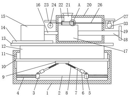
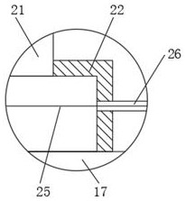
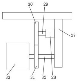
The invention provides a mute noise reduction screw blower, and relates to the technical field of blowers. The mute noise reduction screw air blower comprises a bottom frame, a sliding rod is fixedly connected to the inner wall of the bottom of the bottom frame, sliding blocks are slidably connected to the outer walls of the two sides of the sliding rod, rotating sleeves are fixedly connected to the upper surfaces of the two sliding blocks, telescopic rods are rotatably connected to the upper ends of the rotating sleeves, and shock absorbers are arranged at the bottoms of the telescopic rods. The outer wall of the upper end of the telescopic rod is sleeved with a second spring, the top end of the telescopic rod is rotationally connected with a connecting block, the upper surface of the connecting block is fixedly connected with a connecting plate, the upper surface of the connecting plate is fixedly connected with a sliding column, and the upper surface of the sliding column is fixedly connected with a supporting plate. The left side of the upper surface of the supporting plate is fixedly connected with a motor base. Through the driving effect of the second motor, intermittent movement of the filtering structure can be achieved, then the effect of automatic replacement is achieved, and the situation that the filtering structure is blocked, and use is affected is avoided.
Description
technical field [0001] The invention relates to the technical field of blowers, in particular to a silent and noise-reducing screw blower. Background technique [0002] The blower is mainly composed of the following six parts: motor, air filter, blower body, air chamber, base (and fuel tank), and drip nozzle. The blower operates eccentrically by the biased rotor in the cylinder, and makes the volume change between the vanes in the rotor slot suck, compress and spit out air. During operation, the pressure difference of the blower is used to automatically send lubrication to the drip nozzle, and drip into the cylinder to reduce friction and noise, and at the same time keep the gas in the cylinder from flowing back. This type of blower is also called a sliding vane blower. [0003] The existing blower still has defects during use. Due to the presence of moisture, oil and dust in the air, long-term use will affect the internal structure of the blower and make its noise louder. ...
Claims
Login to View More Application Information
Patent Timeline
 IPC IPC(8): F04C18/16F04C23/02F04C29/00F04C29/06
CPCF04C18/16F04C23/02F04C29/0092F04C29/06F04C29/00
Inventor 牛余会翟荣芝牛联刚刘巧
Owner 山东三牛机械集团股份有限公司
Features
- Generate Ideas
- Intellectual Property
- Life Sciences
- Materials
- Tech Scout
- Unparalleled Data Quality
- Higher Quality Content
- 60% Fewer Hallucinations
Learn More Browse by: Latest US Patents, China's latest patents, Technical Efficacy Thesaurus, Application Domain, Technology Topic, Popular Technical Reports.
© 2025 PatSnap. All rights reserved.Legal|Privacy policy|Modern Slavery Act Transparency Statement|Sitemap|About US| Contact US: help@patsnap.com