


Quick Research
Generate reliable direction feasibility study reports for your R&D in just a few steps.

Technical Q&A
Discover and master advanced knowledge NOW. Basics, ideas, possibilities, all at once.

Find Solutions
As an expert in R&D theories, this can generate solutions to your technical problems instantly.

Evaluate Feasibility
Analyze your overall solution with one click, know your potential R&D risks in advance.

Monitor Landscape
Get weekly tech updates, stay abreast of the latest tech innovations and key insights.
Reaction container conveying device and reaction container supplementary equipment using the same
A technology of a reaction container and a conveying device is applied in the field of supplementary equipment for reaction containers, and can solve the problems of increasing workload, occupying medical space, increasing the overall volume of in vitro diagnostic equipment, etc., and achieving the effect of saving cost and space.
- Summary
- Abstract
- Description
- Claims
- Application Information
AI Technical Summary
Problems solved by technology
Method used
Image

Examples
no. 1 example
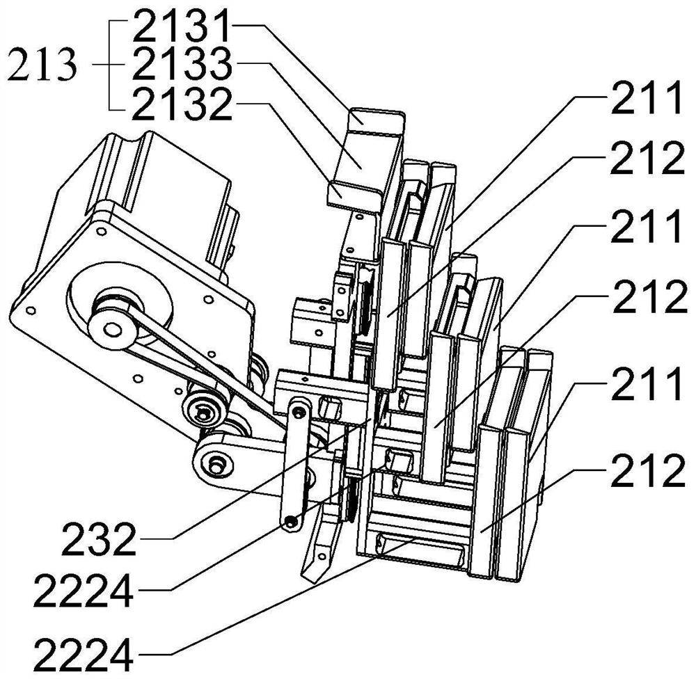
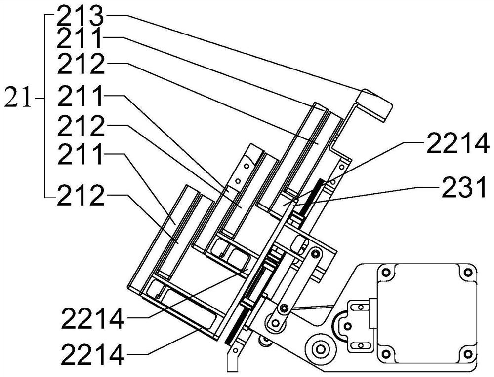
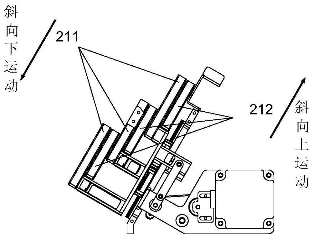
[0061] Please refer to figure 1 - Figure 7 , this embodiment provides a reaction vessel conveying device 2, which includes: a conveying mechanism assembly, a transmission mechanism, a driving mechanism 23 and a conveying channel. The conveying mechanism assembly includes a set of conveying mechanisms 21 , and the conveying mechanism 21 includes a sample feeding plate 211 and a sample receiving plate 212 . The transmission mechanism includes a sample feeding transmission assembly 221 and a sample receiving transmission assembly 222. The sample feeding transmission assembly 221 is used to drive the sample feeding plate 211 to reciprocate, and the sample receiving transmission assembly 222 is used to drive the sample receiving plate 212 to reciprocate. The driving mechanism 23 is used to provide driving force for the transmission mechanism.
[0062] The conveying channel is used for conveying the reaction vessel. The upper sample feeding surface 2113 of the sample feeding plat...
no. 2 example
[0097] This embodiment provides another reaction container conveying device, which is an improved solution of the reaction container conveying device provided in the first embodiment. The difference between the reaction container and the reaction container provided in the first embodiment is that the reaction The conveying mechanism assembly in the container conveying device includes at least two groups of conveying mechanisms. Hereinafter, only the differences of the reaction container conveying device provided in this embodiment will be described, and the same points as the reaction container conveying device provided in the first embodiment will not be repeated.
[0098] Since the conveying mechanism assembly includes at least two groups of conveying mechanisms, correspondingly, in the conveying channel, along the conveying direction, the guiding channel is provided on the downstream side of the sample receiving upper surface 2123 of the most downstream sample receiving plat...
no. 3 example
[0115] This embodiment provides a reaction vessel replenishing device, which includes the reaction vessel conveying device 2 as provided in the first or second embodiment above.
[0116] like Figure 19 - Figure 21 As shown, in a preferred implementation of this embodiment, the reaction vessel replenishing device further includes: a reaction vessel receiving device 4 , a reaction vessel pushing device 3 and a reaction vessel pushing device 5 . The conveying mechanism 21 receives the reaction container 1 pushed out by the reaction container pushing device 3 , and the reaction container receiving device 4 receives the reaction container 1 conveyed through the conveying channel. The reaction vessel conveying device 2 has a first feeding end 25 and a first discharging end 26; the reaction vessel receiving device 4 has a second feeding end, a second discharging end a and a second discharging end b; the reaction vessel The pushing device 3 has a third feeding end 31 and a third d...
PUM
 Abstract
Description
Claims
Application Information
 - R&D Engineer
- R&D Manager
- IP Professional
- Industry Leading Data Capabilities
- Powerful AI technology
- Patent DNA Extraction
Browse by: Latest US Patents, China's latest patents, Technical Efficacy Thesaurus, Application Domain, Technology Topic, Popular Technical Reports.
© 2024 PatSnap. All rights reserved.Legal|Privacy policy|Modern Slavery Act Transparency Statement|Sitemap|About US| Contact US: help@patsnap.com