
Nozzle rotating double-spray-head type cement 3D printing structure and using method thereof

A 3D printing and nozzle-type technology, applied in cement mixing devices, chemical instruments and methods, cleaning methods and appliances, etc., can solve problems such as low automation, uneven cement pouring, and high cost

Active Publication Date: 2021-04-30
江苏集萃复合材料装备研究所有限公司
View PDF6 Cites 1 Cited by
  • Summary
  • Abstract
  • Description
  • Claims
  • Application Information

AI Technical Summary

Problems solved by technology

[0004] In the existing technology, there are few equipments that can be really applied to 3D printing buildings, and they are very expensive. It is an urgent demand in the market to develop equipment matching new 3D printing building materials; the automation degree of existing 3D printing equipment is relatively low, and most of them are With manual control construction, it is necessary to set the splint of the construction model in advance, and then manually control the 3D printing equipment to pour cement; this method requires operators to have certain construction experience, and improper operation may lead to uneven cement pouring and affect the construction quality

Method used


Image

  • Nozzle rotating double-spray-head type cement 3D printing structure and using method thereof
  • Nozzle rotating double-spray-head type cement 3D printing structure and using method thereof
  • Nozzle rotating double-spray-head type cement 3D printing structure and using method thereof

Examples


Embodiment Construction

[0039] The specific implementation manner of the present invention will be described below in conjunction with the accompanying drawings.

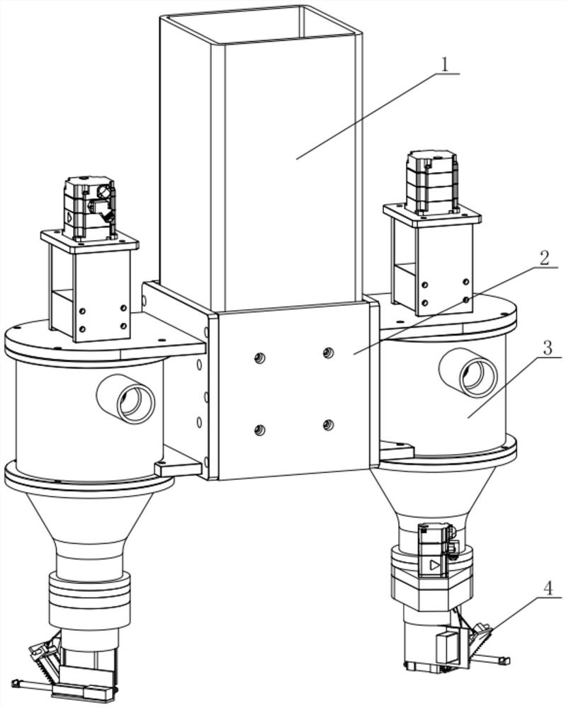
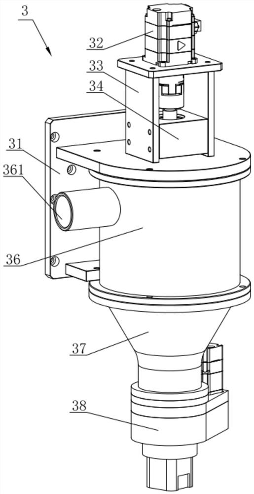
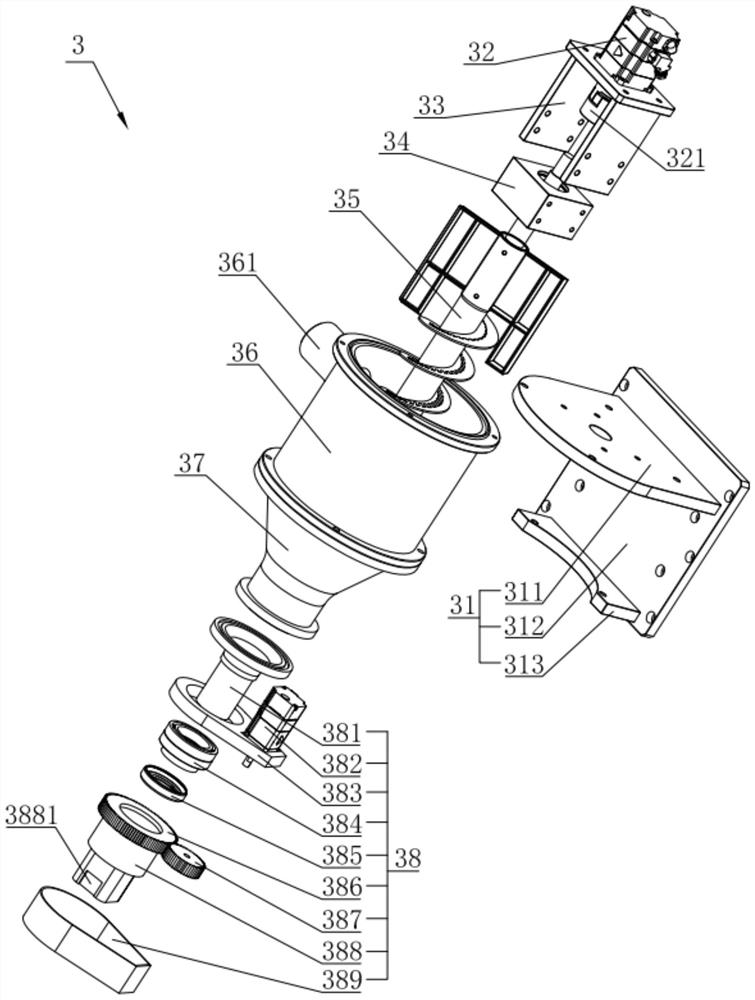
[0040] Such as figure 1 As shown, a nozzle rotating dual-nozzle cement 3D printing structure in this embodiment includes a column 1, and a nozzle assembly 3 is symmetrically installed on the side of the column 1; figure 2 , image 3 and Figure 4 As shown, the structure of the single group nozzle assembly 3 is as follows: it includes a support base 31 fixed on the side of the column 1, a feed cylinder 36 is fixed on the outside of the support base 31, a motor base 33 is installed above the feed cylinder 36, and the motor base 33 A feeding motor 32 is installed on the top, the output end of the feeding motor 32 faces down and a screw shaft 35 is installed at the end, and the screw shaft 35 extends downward into the feeding barrel 36; the bottom of the feeding barrel 36 is equipped with a connected extrusion barrel 37. The bottom of the ...


PUM


Abstract

The invention relates to a nozzle rotating double-spray-head type cement 3D printing structure and a using method thereof. The nozzle rotating double-spray-head type cement 3D printing structure comprises a stand column, and spray head assemblies are symmetrically installed on the side face of the stand column. Each set of spray head assembly comprises a supporting base fixedly installed on the stand column, a feeding cylinder is fixedly installed on the outer side of each supporting base, a feeding motor is installed above each feeding cylinder, a spiral shaft is installed at the downward output end of each feeding motor, and each spiral shaft stretches downwards into the corresponding feeding cylinder. A communicating extrusion cylinder is mounted at the bottom of each feeding cylinder, and a nozzle piece is mounted at the bottom of each extrusion cylinder through a nozzle rotating assembly. A feeding hole is formed in the upper part of the side wall of each feeding cylinder and is connected with an external cement conveying pump through a hose. An automatic cutting and sealing mechanism is mounted on the outer side wall of each nozzle piece. Cement enters the feeding cylinders through the hoses under the action of the cement conveying pumps, the spiral shafts rotate to extrude the cement downwards, and the nozzle rotating assemblies drive the nozzle pieces to rotate relative to the extrusion cylinders. The two sets of spray head assemblies cooperate with each other or work independently, are suitable for printing components of various shapes or colors, and are good in practicability and high in use flexibility.

Description

technical field [0001] The invention relates to the technical field of cement 3D printing equipment, in particular to a cement 3D printing structure with rotating nozzles and double nozzles and a method for using the same. Background technique [0002] 3D printing is a rapid prototyping technology that uses some adhesive materials to construct models by printing them layer by layer. Mold manufacturing and industrial design industries are used to build models, and are gradually developing into product manufacturing, forming "direct digital manufacturing", so 3D printing is also called rapid prototyping, additive manufacturing, and laminated manufacturing. [0003] The 3D printing technology with the highest processing precision is light-curing printing technology. The printing material is usually photosensitive resin. The resin undergoes a curing reaction under a certain wavelength of laser light. To a line, and then extended from a line to a surface, so as to complete the p...

Claims


Application Information

Patent Timeline
Patent Type & Authority Applications(China)
IPC IPC(8): B28B1/00B28C5/16B33Y30/00B08B9/087
CPCB28B1/001B33Y30/00B28C5/16B08B9/087
Inventor 李思奇张秋菊宁萌
Owner 江苏集萃复合材料装备研究所有限公司
Learn More