A new energy intelligent battery control core fully automatic intelligent manufacturing equipment

A technology of smart batteries and control cores, applied in secondary battery manufacturing, manufacturing tools, battery assembly machines, etc., can solve problems affecting product processing quality, low labor efficiency, affecting production efficiency, etc., and achieve good market application value , the effect of reducing manual labor and increasing production efficiency

Active Publication Date: 2021-12-10
深圳特威新能源有限公司
View PDF8 Cites 0 Cited by
  • Summary
  • Abstract
  • Description
  • Claims
  • Application Information

AI Technical Summary

Problems solved by technology

[0002] At present, the country actively recommends the development of new energy, and the use of new energy is becoming more and more common. In electric vehicles, smart batteries are the main energy supply point, and the production process of each part is particularly important. The traditional battery lock screw The method is mostly manual operation, but there is a large error range in manual operation, which affects the processing quality of the product, the manual work efficiency is low, and the production cost is increased; now, the electric screwdriver is used to lock the screw, although the manual operation is reduced. Labor-intensive, but human operation has inaccurate positioning. When the electric screwdriver is used for a long time, the bit will shake, which may cause problems such as screw tooth damage or screw lock not in place, which will affect the processing of the battery. quality, resulting in loosening and falling off of the locking screw, which affects the service life, and also requires manual placement of screws and handling of processed parts, which affects production efficiency and has a high defect rate

Method used


Image

  • A new energy intelligent battery control core fully automatic intelligent manufacturing equipment
  • A new energy intelligent battery control core fully automatic intelligent manufacturing equipment
  • A new energy intelligent battery control core fully automatic intelligent manufacturing equipment

Examples


Embodiment approach

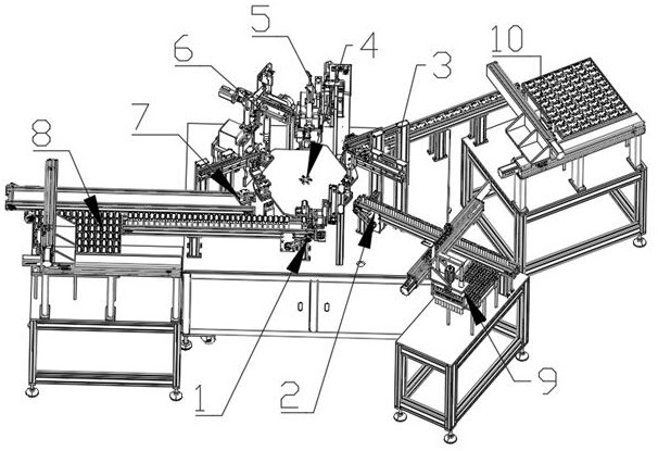
[0024] Such as Figure 1-Figure 4 One embodiment described: a new energy intelligent battery control core automatic intelligent manufacturing equipment, including a work frame, a first mobile frame, a second mobile frame and a third mobile frame, the first mobile frame is set in relation to the The left side of the work frame, the second mobile frame is arranged on the front side of the work frame, the third mobile frame is arranged on the right side of the work frame, and the shell feeding device 1 and the battery are respectively arranged on the work frame. Feeding device 2, top cover feeding device 3, rotating device 4, first locking device 5, second locking device 6 and unloading device 7, the rotating device 4 is arranged in the middle of the working frame, the Shell feeding device 1, battery feeding device 2, top cover feeding device 3, first locking device 5, second locking device 6 and unloading device 7 are arranged in the counterclockwise direction around the rotatin...

Embodiment 2

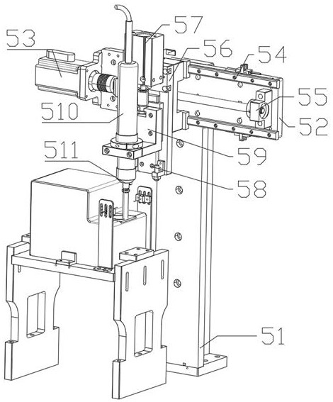
[0033] The difference between the second embodiment and the above is that the lift slide plate 59 is L-shaped.

Embodiment 3

[0034] The third embodiment is different from the above in that the rotating device 4 includes a rotating motor, a rotating rod, a reduction box, a rotating disk and a plurality of fixed seats, and the rotating motor and the reduction box are all arranged on the work frame, and the rotating The motor is connected to the reduction box, the bottom of the rotating rod is arranged in the middle of the reduction box, the top of the rotating rod is arranged on the lower surface of the rotating disk, and a plurality of fixing seats are arranged on the upper surface of the rotating disk.


PUM


Abstract

The invention discloses a new energy intelligent battery control core automatic intelligent manufacturing equipment, which includes a working frame, a first moving frame, a second moving frame and a third moving frame, the first moving frame is set on the left side of the working frame, and the second The mobile frame is set on the front side of the working frame, the third mobile frame is set on the right side of the working frame, and the working frame is respectively equipped with a shell feeding device, a battery feeding device, a top cover feeding device, a rotating device, a first locking device, The second locking device and unloading device, the rotating device is set in the middle of the working frame, the shell loading device, the battery loading device, the top cover loading device, the first locking device, the second locking device and the unloading device in sequence Arranged counterclockwise to the periphery of the rotating device, the first mobile frame is provided with a shell transfer assembly, the second mobile frame is provided with a battery transfer assembly, and the third mobile frame is provided with a top cover transfer assembly, reducing Artificial labor increases production efficiency and reduces defective rate, which has good market application value.

Description

technical field [0001] The invention relates to the field of battery processing, in particular to a new energy intelligent battery control core automatic intelligent manufacturing equipment. Background technique [0002] At present, the country actively recommends the development of new energy, and the use of new energy is becoming more and more common. In electric vehicles, smart batteries are the main energy supply point, and the production process of each part is particularly important. The traditional battery lock screw The method is mostly manual operation, but there is a large error range in manual operation, which affects the processing quality of the product, the manual work efficiency is low, and the production cost is increased; now, the electric screwdriver is used to lock the screw, although the manual operation is reduced. Labor-intensive, but human operation has inaccurate positioning. When the electric screwdriver is used for a long time, the bit will shake, w...

Claims


Application Information

Patent Timeline
Patent Type & Authority Patents(China)
IPC IPC(8): B23P19/06B23P19/00H01M10/04
CPCB23P19/06B23P19/007H01M10/0404Y02P70/50
Inventor 马学涛陈宇朱超群姚金才
Owner 深圳特威新能源有限公司
Why Eureka
Try Eureka