
Blood separation device based on acoustic fluid mechanics

A fluid mechanics and blood separation technology, applied in the field of biomedicine, can solve the problems of cumbersome operation, time-consuming, high cost, etc., and achieve the effect of strong controllability

Pending Publication Date: 2021-04-30
GENERAL HOSPITAL OF NINGXIA MEDICAL UNIV
View PDF0 Cites 3 Cited by
  • Summary
  • Abstract
  • Description
  • Claims
  • Application Information

AI Technical Summary

Problems solved by technology

[0003] The traditional bacterial isolation technology is to culture and isolate in agar medium, which takes a lot of time and requires operators to have a high technical level
At present, the centrifugal technology is often used to separate the samples. However, the samples often rupture due to the excessive centrifugal force during the operation, resulting in cell inactivation; and during the separation, the equipment needs to be turned on and off frequently to Observe the sample and understand the progress of sample separation, which also increases the operating burden of the equipment and shortens the service life of the equipment; moreover, the centrifuge technology needs to manually take the test tube for observation, which is not only cumbersome to operate, but also increases the test time. The risk of sample contamination will affect the separation effect of the sample; moreover, the separation accuracy of centrifugal technology is low
[0004] In addition, there is a separation method based on optical tweezers technology, but long-term laser irradiation will generate a large amount of heat, thereby damaging the activity of the sample; while the method based on magnetic field technology requires the object to be operated to be magnetic; and the above two methods The system is complex and expensive, so the above two methods are less practical

Method used


Image

  • Blood separation device based on acoustic fluid mechanics
  • Blood separation device based on acoustic fluid mechanics
  • Blood separation device based on acoustic fluid mechanics

Examples


Embodiment Construction

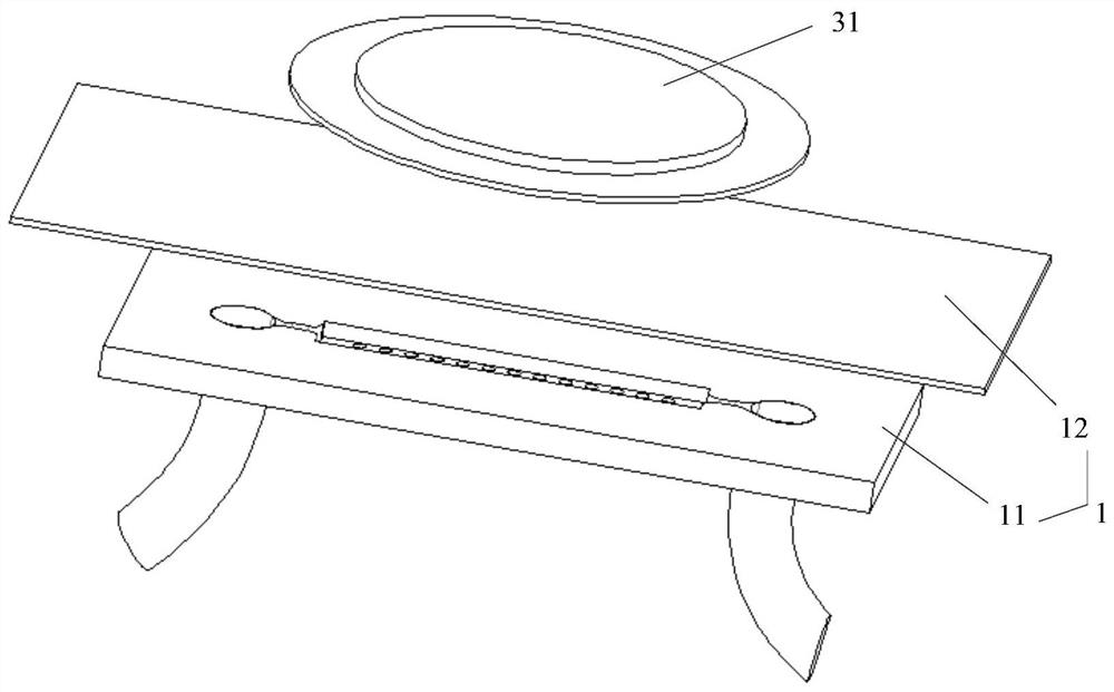
[0030] The technical solutions in the embodiments of the present application will be fully and clearly described below in conjunction with the drawings in the embodiments of the present application. Apparently, the described embodiments are only some of the embodiments of this application, not all of them. Based on the embodiments in this application, all other embodiments obtained by persons of ordinary skill in the art without making creative efforts belong to the scope of protection of this application.

[0031] see figure 1 , is the application scenario diagram provided by the embodiment of this application. An embodiment of the present application provides a blood separation device based on acoustohydrodynamics, including: a microfluidic chip 1 , a microfluidic pump 2 and an acoustic wave drive system 3 . In actual use, the microfluidic chip 1 is set on the microscope stage, the microfluidic pump 2 is connected to the microfluidic chip 1 through a hose, and the piezoele...


PUM

PropertyMeasurementUnit
lengthaaaaaaaaaa
widthaaaaaaaaaa
depthaaaaaaaaaa

Abstract

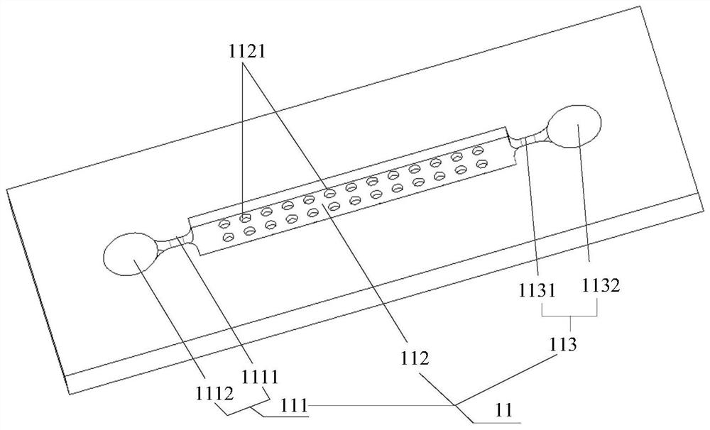
The invention relates to the technical field of biomedicine, and provides a blood separation device based on acoustic fluid mechanics. The blood separation device comprises a micro-fluidic chip, a micro-fluidic pump and a sound wave driving system, wherein the micro-fluidic pump is connected with the micro-flow channel of the micro-fluidic chip through a hose, micropores distributed in an array mode are formed in the bottom face of the micro-flow channel, the piezoelectric transducer of the sound wave driving system is fixed to the glass substrate of the micro-fluidic chip, microfluid enters the micro-flow channel under the action of the micro-fluidic pump, particles in the microfluid are separated according to different acoustic flow field forces borne by the particles with different particle sizes in an acoustic flow field, and by controlling the acoustic flow capture force borne by the particles and the thrust of an external flow field, the particles with relatively large particle sizes are captured by the micropores, and the particles with relatively small particle sizes migrate along with the flow field. According to the blood separation device, particles in blood are not damaged, the controllability is high, and target bacteria can be simply and efficiently separated from the blood.

Description

technical field [0001] The present application relates to the field of biomedical technology, in particular to a blood separation device based on acoustohydrodynamics. Background technique [0002] Bacterial infection often causes a variety of diseases, not only has a high incidence rate but also often leads to critical illness, so timely diagnosis and treatment are required. At present, most of the root causes of bacterial diseases need to isolate specific bacteria from a mixture of cells and bacteria (such as blood), and then analyze and process the specific bacteria. Therefore, bacterial isolation technology has great significance in clinical medicine, bioengineering and other fields. significance. [0003] The traditional bacterial isolation technology is to culture and isolate bacteria in agar medium, which takes a lot of time and requires operators to have a high technical level. At present, the centrifugal technology is often used to separate the samples. However, t...

Claims


Application Information

Patent Timeline
Patent Type & Authority Applications(China)
IPC IPC(8): B01L3/00G01N1/28
CPCB01L3/50273B01L3/502753B01L2400/0436G01N1/28
Inventor 赵志军冯林
Owner GENERAL HOSPITAL OF NINGXIA MEDICAL UNIV
Learn More