Method and device for simultaneously measuring reflection and transmission distortion difference of optical element

A technology of reflective transmission and optical components, applied in the field of optical measurement, can solve problems that affect the accuracy of measurement, inaccurate measurement results, and increase system complexity

Active Publication Date: 2021-04-27
NAT UNIV OF DEFENSE TECH
View PDF6 Cites 5 Cited by
  • Summary
  • Abstract
  • Description
  • Claims
  • Application Information

AI Technical Summary

Problems solved by technology

There are two main problems in this measurement method. One is that more optical components will be introduced into the strong light emission path, which will increase the complexity of the system and increase the system error; the other is that the difference between two different Hartmann sensors

Method used


Image

  • Method and device for simultaneously measuring reflection and transmission distortion difference of optical element
  • Method and device for simultaneously measuring reflection and transmission distortion difference of optical element
  • Method and device for simultaneously measuring reflection and transmission distortion difference of optical element

Examples


Embodiment Construction

[0036] The present invention will be further described below in conjunction with the accompanying drawings and specific embodiments.

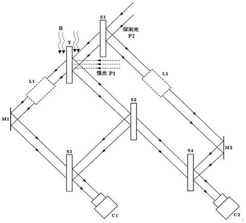
[0037]refer to figure 2 , this embodiment provides a device for simultaneously measuring reflection and transmission distortion of optical elements, including a detection light source P2, a first half mirror S1, a second half mirror S2, a third half mirror S3, The first optical path difference adjusting mechanism L1, the first mirror M1 and the first camera C1.

[0038] The detection light source P2 is incident on the first half-mirror S1 at an incident angle of 45°, and the first half-mirror S1 is parallel to the sample T to be tested. In this embodiment, the sample T to be tested has a flat front and rear surface. Plane mirror. The transmitted light transmitted by the first half-mirror S1 is used as the probe light, and the probe light is incident on the sample T to be tested at an incident angle of 45°, and after passing through the sampl...


PUM


Abstract

The invention relates to a method and device for simultaneously measuring the reflection and transmission distortion difference of an optical element. The method comprises the steps: enabling a detection light source to enter a first half-transparent and half-reflecting mirror which is parallel to a to-be-measured sample, enabling transmission light transmitted by the first half-transparent and half-reflecting mirror to serve as detection light, enabling the detection light to enter the to-be-measured sample, and dividing the detection light into reflected light and transmission light, wherein light paths corresponding to the reflected light and the transmitted light are respectively called as a reflecting arm and a transmitting arm, and a light beam on the transmitting arm passes through a first optical path difference adjusting mechanism and a first reflecting mirror and then enters a second semi-transparent semi-reflecting mirror; the light beam reflected by the third semi-transparent semi-reflective mirror enters the second semi-transparent semi-reflective mirror and interferes with the light beam entering the transmission arm of the second semi-transparent semi-reflective mirror, and the light beam is acquired by the first camera and imaged into interference fringes. According to the invention, the deformation of the front surface and the rear surface of the highlight optical element can be quantitatively and reversely deduced on line in real time, the result is accurate, and the optical path difference between transmitted light and reflected light can be measured through a single camera.

Description


Claims


Application Information

Patent Timeline
Owner NAT UNIV OF DEFENSE TECH
Why Eureka
Try Eureka