Machining surface roughening milling cutter and machining surface machining method thereof

A surface roughening and milling cutter technology, which is applied to milling cutters, metal processing equipment, milling machines, etc., can solve the problems of insufficient roughening, long time-consuming machining of surface roughening, and difficulty in achieving adhesion.

Active Publication Date: 2021-04-27
ZHUHAI RUNXINGTAI ELECTRICAL
View PDF9 Cites 0 Cited by
  • Summary
  • Abstract
  • Description
  • Claims
  • Application Information

AI Technical Summary

Problems solved by technology

However, this method takes a long time to roughen the machined surface, and the degree of roughening is not thorough enough to meet the requirements of adhesion

Method used


Image

  • Machining surface roughening milling cutter and machining surface machining method thereof
  • Machining surface roughening milling cutter and machining surface machining method thereof
  • Machining surface roughening milling cutter and machining surface machining method thereof

Examples


Embodiment Construction

[0029] In order to make the object, technical solution and advantages of the present invention clearer, the present invention will be further described in detail below in conjunction with the accompanying drawings.

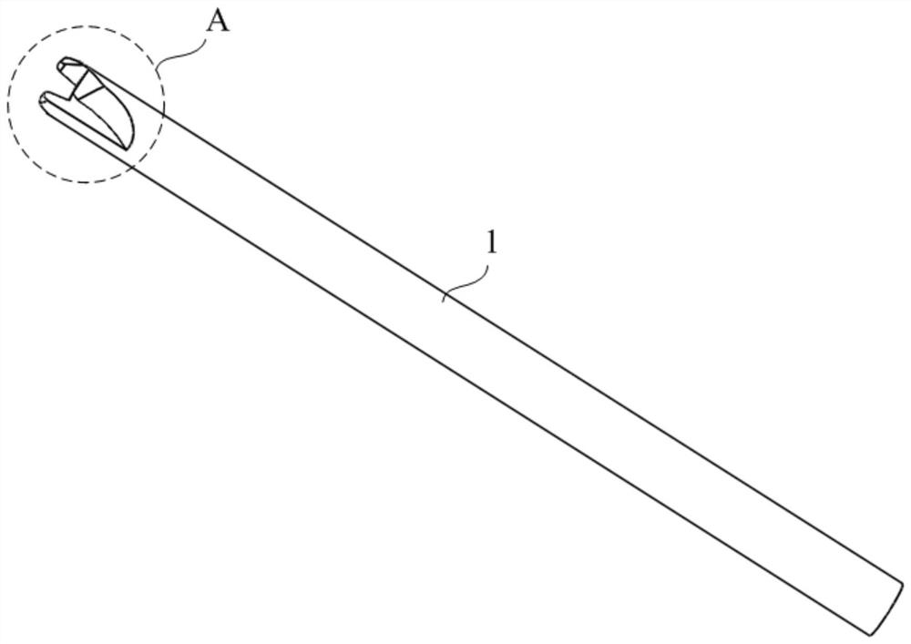
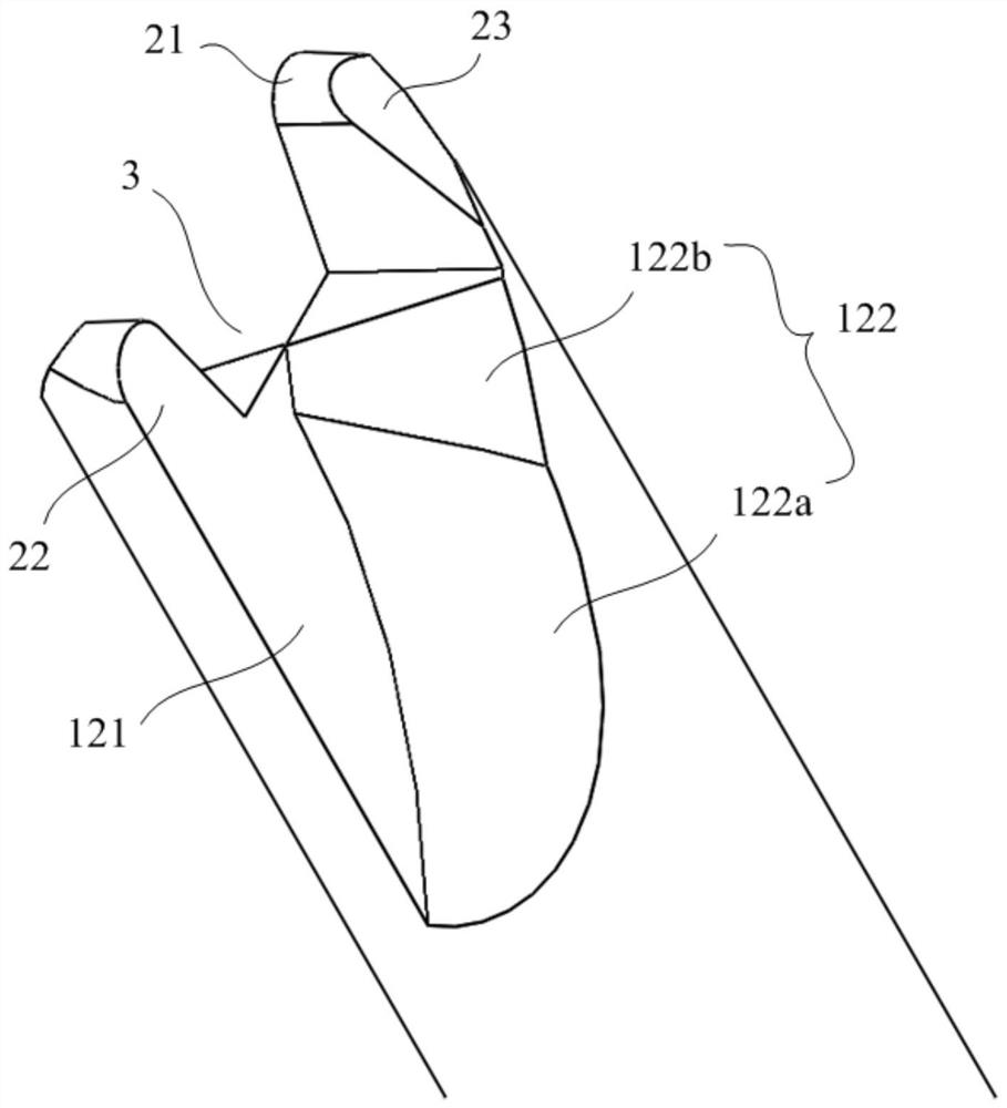
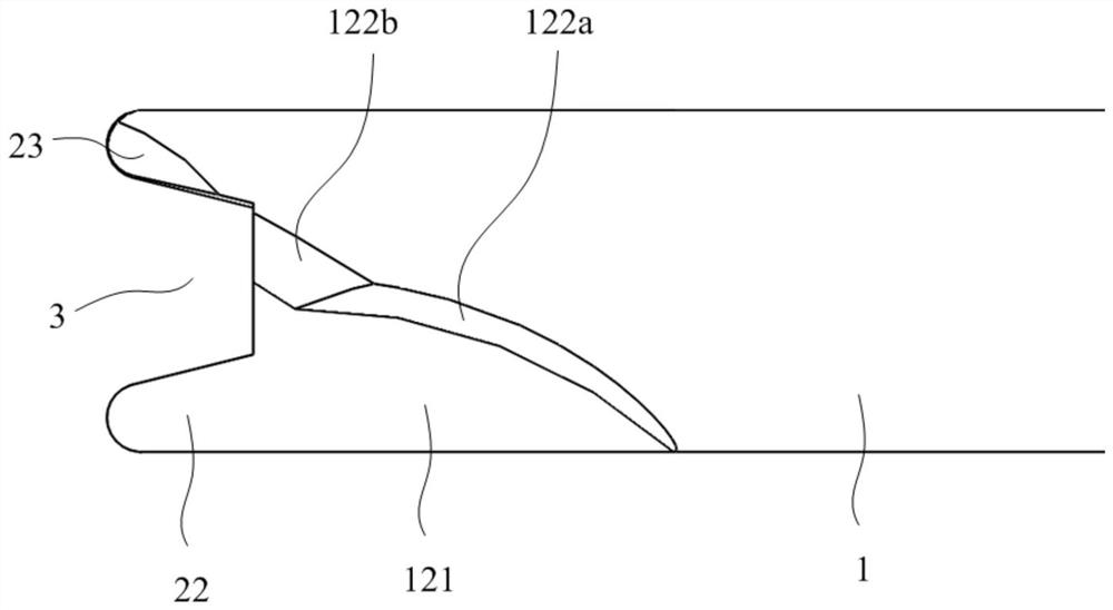
[0030] Such as figure 1 , figure 2 , image 3 with Figure 4 As shown, this embodiment provides an embodiment of a machined surface roughening milling cutter, including a cutter body 1 and at least two cutter teeth 2, the cutter teeth 2 are formed at the end of the cutter body 1, and the cutter An avoidance groove 3 is formed between the teeth 2 and the end face 11 of the cutter body, and a chip removal groove 12 communicating with the avoidance groove 3 is formed on the outer periphery of the cutter body 1; wherein, the width of the end face 21 of the cutter tooth is 0.3- 1.1mm; the height of the cutter teeth 2 is 1.5-3.8mm; the relief groove 3 is open to the cutter tooth end face 21 side, and the ratio of the width of the groove bottom of the relief groove 3...


PUM

PropertyMeasurementUnit
diameteraaaaaaaaaa

Abstract

The invention discloses a machining surface roughening milling cutter and a machining surface machining method thereof. The machining surface roughening milling cutter comprises a cutter body and at least two cutter teeth, wherein the cutter teeth are formed at the end of the cutter body, receding grooves are formed between the cutter teeth and the end face of the cutter body, and chip grooves communicating with the receding grooves are formed in the periphery of the cutter body; the width of the end face of each cutter tooth ranges from 0.3 mm to 1.1 mm; the height of the cutter teeth ranges from 1.5 mm to 3.8 mm; and the receding grooves are opened towards one sides of the end faces of the cutter teeth, the ratio of the width of the groove bottoms of the receding grooves to the diameter of the cutter body is 0.7-1.2: 2, and an included angle between the groove walls of the receding grooves and the axis of the cutter body is 10 degrees-18 degrees. The machining surface roughening milling cutter is high in roughening machining efficiency, the roughening degree of a machining surface is high, and the attachment effect between the machining surface roughening milling cutter and heat conduction silica gel or heat conduction gel is good.

Description

technical field [0001] The invention relates to the technical field of palletizing equipment for packaging boxes of sanitary ware, in particular to a machined surface roughening milling cutter and a machined surface processing method thereof. Background technique [0002] At present, when assembling many communication products, radiators, 5G products, etc., it is necessary to paste thermal silica gel or thermal gel on specific machined surfaces. [0003] However, the roughness of the machined surface produced by CNC milling is below Ra3.2, which may easily cause the thermally conductive silica gel or thermally conductive gel attached to the machined surface to slide and fall off. [0004] In order to increase the surface roughness of the machined surface, a ball cutter is usually used to reciprocate on the machined surface to mill out the form pattern to achieve the effect of increasing the surface roughness. However, this method takes a long time to roughen the machined su...

Claims


Application Information

Patent Timeline
Patent Type & Authority Applications(China)
IPC IPC(8): B23C5/10B23C1/00
CPCB23C5/10B23C1/00
Inventor 张莹梁绍钜肖先智王继成蓝志平任怀德
Owner ZHUHAI RUNXINGTAI ELECTRICAL
Why Eureka
Try Eureka