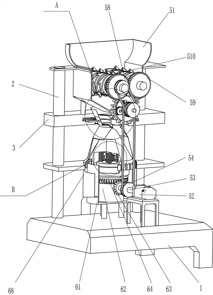
Board machining waste grinding device
A grinding device and plate processing technology, which is applied in the direction of grain processing, etc., can solve the problems of affecting follow-up work, easily raising dust to affect the surrounding environment, and not being able to completely crush, etc.
- Summary
- Abstract
- Description
- Claims
- Application Information
AI Technical Summary
Problems solved by technology
Method used
Image
Examples
Embodiment 1
[0028] A plate processing waste grinding device, such as Figure 1-Figure 5 As shown, it includes a base 1, a support column 2, a fixed plate 3, a support plate 4, a crushing mechanism 5 and a grinding mechanism 6, and four support columns 2 are fixedly connected at intervals on the left side of the top of the base 1, and between the four support columns 2 There are three fixed plates 3 fixedly connected, and the support plate 4 is fixed symmetrically on the front right side of the top of the base 1. There is a crushing mechanism 5 between the base 1 and the fixed plate 3, and there is also a grinding mechanism between the base 1 and the fixed plate 3. Institution 6.
[0029] The crushing mechanism 5 includes a lower hopper 51, a first motor 52, a drive shaft 53, a first transmission assembly 54, a fixed shaft 55, a movable sleeve 56, a reduction planetary gear 57, a second transmission assembly 58, a transmission gear assembly 59 and a crushing mechanism. Roller 510, the low...
Embodiment 2
[0035] On the basis of Example 1, such as figure 1 , figure 2 , Figure 4 , Image 6 and Figure 7 As shown, a stirring mechanism 7 is also included, and the stirring mechanism 7 includes a mounting plate 71, a rotating central shaft 72, a spiral fan blade 73, a stirring baffle 74, a rotating force rod 75 and a driving circular plate 76, and the inside of the middle fixed plate 3 The symmetrical mounting plate 71 is fixedly connected, and the middle part of the mounting plate 71 on the upper and lower sides is rotatably provided with a rotating central shaft 72, and the middle part of the rotating central shaft 72 is fixedly connected with a spiral fan blade 73 in the circumferential direction, and the middle fixed plate 3 is internally rotated. Stirring baffles 74 are arranged, and the middle part of the inner side of the stirring baffle 74 is fixedly connected with the spiral fan blade 73 in the circumferential direction. The middle part of the outer side of the stirring...
Embodiment 3
[0040] On the basis of embodiment 1 and embodiment 2, such as figure 1 , Image 6 and Figure 8 As shown, a protective mechanism 9 is also included. The protective mechanism 9 includes a mounting seat 91, a fixed shaft 92 and a protective cover 93. The top left side of the uppermost fixed plate 3 is symmetrically fixed with the mounting seat 91 in the middle of the left side. Between the 91 tops, a fixed shaft 92 is rotatably arranged, and a protective cover 93 is affixed to the circumference of the middle part of the fixed shaft 92 .
[0041] Also includes a blanking mechanism 10, the blanking mechanism 10 includes a blanking screen cylinder 101, a cloth cover 102 and a blanking frame 103, and a blanking screen cylinder is fixedly connected between the bottom of the blanking pipe 69 and the left side of the front side of the base 1 101, a cloth cover 102 is fixedly connected to the bottom of the blanking screen cylinder 101, and a blanking frame 103 is slidably placed on th...
PUM
 Abstract
Description
Claims
Application Information
 - Generate Ideas
- Intellectual Property
- Life Sciences
- Materials
- Tech Scout
- Unparalleled Data Quality
- Higher Quality Content
- 60% Fewer Hallucinations
Browse by: Latest US Patents, China's latest patents, Technical Efficacy Thesaurus, Application Domain, Technology Topic, Popular Technical Reports.
© 2025 PatSnap. All rights reserved.Legal|Privacy policy|Modern Slavery Act Transparency Statement|Sitemap|About US| Contact US: help@patsnap.com


