
Welding device for pipeline sealing connection

A welding device and pipeline sealing technology, which is applied in the direction of auxiliary devices, welding equipment, auxiliary welding equipment, etc., can solve the problems of small working range, low service life, and low degree of automation, so as to improve stability and reliability, reduce Effect of friction and stability improvement

Active Publication Date: 2019-03-08
纳木博(常州)智能装备有限公司
View PDF10 Cites 18 Cited by
  • Summary
  • Abstract
  • Description
  • Claims
  • Application Information

AI Technical Summary

Problems solved by technology

[0002] Pipeline welding in the prior art generally uses manual welding, which is complex in operation, low in automation, and low in deposition efficiency. The welded pipeline cannot well meet the needs of actual construction, and its service life is low.
[0003] Therefore, pipeline welding equipment has appeared. The existing pipeline welding equipment generally places the pipeline horizontally for welding. Time is not flexible enough and the scope of work is small

Method used


Image

  • Welding device for pipeline sealing connection
  • Welding device for pipeline sealing connection
  • Welding device for pipeline sealing connection

Examples


Embodiment Construction

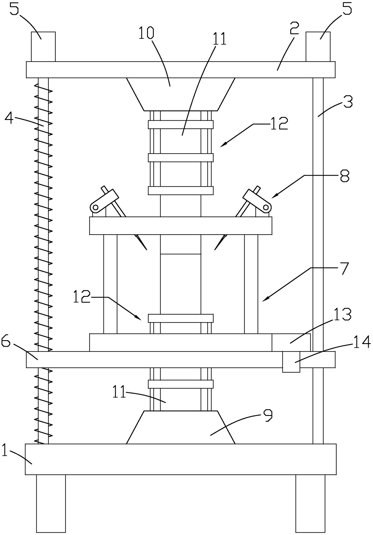
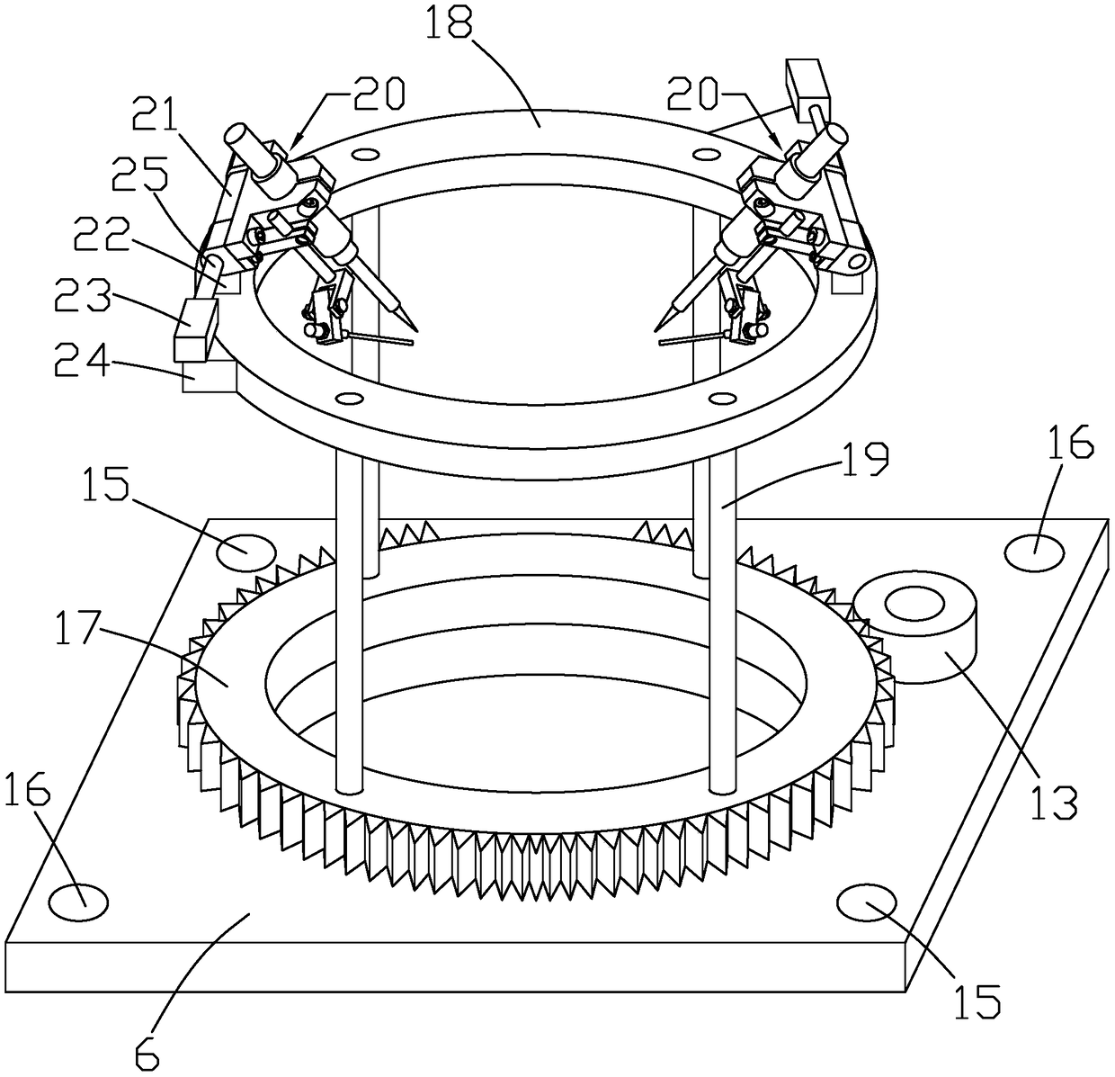
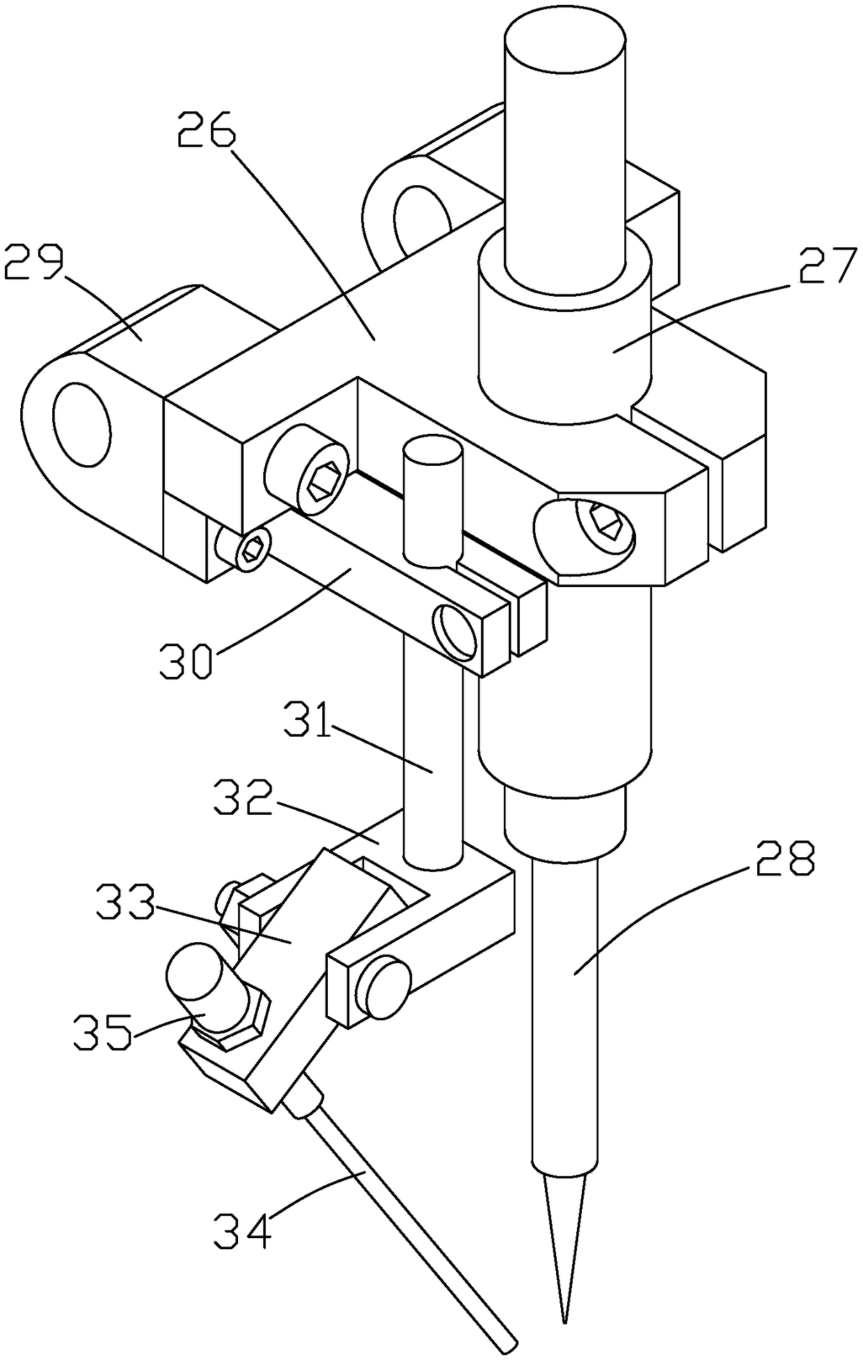
[0032] like Figure 1 to Figure 6 As shown, it is a welding device for pipeline sealing connection according to the present invention, which includes a base 1, a positioning plate 2, a rotating mechanism 7, a welding mechanism 8 and a clamping positioning mechanism 12. The positioning plate 2 is connected by the column 3 and the screw 4. The top of the screw 4 is provided with a first motor 5, and the first motor 5 is located on the top surface of the positioning plate 2. A lifting plate 6 is moved between the column 3 and the screw 4. The plate 6 is provided with a first through hole 15 and a second through hole 16, the column 3 matches the first through hole 15, the screw 4 matches the second through hole 16, the first through hole 15 and the second through hole 16 The design improves the stability of the lifting plate 6 in the process of moving up and down.

[0033] The rotating mechanism 7 is rotatably connected to the lifting plate 6. The rotating mechanism 7 includes a ...


PUM


Abstract

The invention discloses a welding device for pipeline sealing connection. The welding device for pipeline sealing connection comprises a base, a locating plate, a rotating mechanism, a welding mechanism and clamping and locating mechanisms. The base is connected with the locating plate through a stand column and a threaded rod. First motors are arranged at the top end of the threaded rod, and a lifting plate is connected between the stand column and the threaded rod in a moving mode. The rotating mechanism is connected to the lifting plate in a rotating mode, and the welding mechanism is connected to the rotating mechanism. A lower locating platform and an upper locating platform are arranged on the top surface of the base and the bottom surface of the locating plate correspondingly, and the clamping and locating mechanisms are arranged on the lower locating platform and the upper locating platform. Two pipeline test pieces are limited in the upper clamping and locating mechanism and the lower clamping and locating mechanism correspondingly and located on the same vertical straight line. The welding device for pipeline sealing connection is simple in structure and high in practicability, can conduct clamping and locating operation on two pipelines in the up-and-down direction, and can also adjust the height and the position of a welding mechanism, the requirement for sealing welding of pipelines with different lengths is met, the practicability of the welding device is greatly improved, and the working range of the welding device is greatly broadened.

Description

technical field [0001] The present invention relates to a welding device for pipeline sealing connection. Background technique [0002] The pipeline welding in the prior art generally adopts manual welding, which is complicated in operation, low in automation and low in deposition efficiency. The welded pipeline cannot well meet the needs of actual construction and has a low service life. [0003] Therefore, pipeline welding equipment has appeared. The existing pipeline welding equipment generally welds the pipeline horizontally. This welding method makes the two pipelines not fit tightly, and it is very easy to produce false welding and missing welding during welding. not flexible enough, and the scope of work is small. SUMMARY OF THE INVENTION [0004] The purpose of the present invention is to provide a technical solution for a welding device for pipeline sealing connection in view of the shortcomings of the prior art, which can not only clamp and position two pipeline...

Claims


Application Information

Patent Timeline
Patent Type & Authority Applications(China)
IPC IPC(8): B23K37/00B23K37/02B23K37/053
CPCB23K37/00B23K37/02B23K37/0211B23K37/053
Inventor 支黎锋
Owner 纳木博(常州)智能装备有限公司
Learn More