
Complex dielectric constant measurement method, radio frequency device, integrated circuit and radio device

A technology of complex dielectric constant and measurement method, applied in the field of electronics, can solve the problems affecting product design, debugging and production, the difference of complex dielectric constant of microwave medium, etc., and achieve the effect of intuitive effect, simple operation and high precision.

Active Publication Date: 2021-04-20
CALTERAH SEMICON TECH SHANGHAI CO LTD
View PDF16 Cites 2 Cited by
  • Summary
  • Abstract
  • Description
  • Claims
  • Application Information

AI Technical Summary

Problems solved by technology

Different manufacturers or different batches of microwave dielectrics of the same manufacturer often have different complex dielectric constants, which affect product design, debugging and production

Method used


Image

  • Complex dielectric constant measurement method, radio frequency device, integrated circuit and radio device
  • Complex dielectric constant measurement method, radio frequency device, integrated circuit and radio device
  • Complex dielectric constant measurement method, radio frequency device, integrated circuit and radio device

Examples


Embodiment Construction

[0073] The application will be further described in detail below in conjunction with the accompanying drawings and embodiments. It should be understood that the specific embodiments described here are only used to explain the present application, but not to limit the present application. In addition, it should be noted that, for the convenience of description, only some structures related to the present application are shown in the drawings but not all structures.

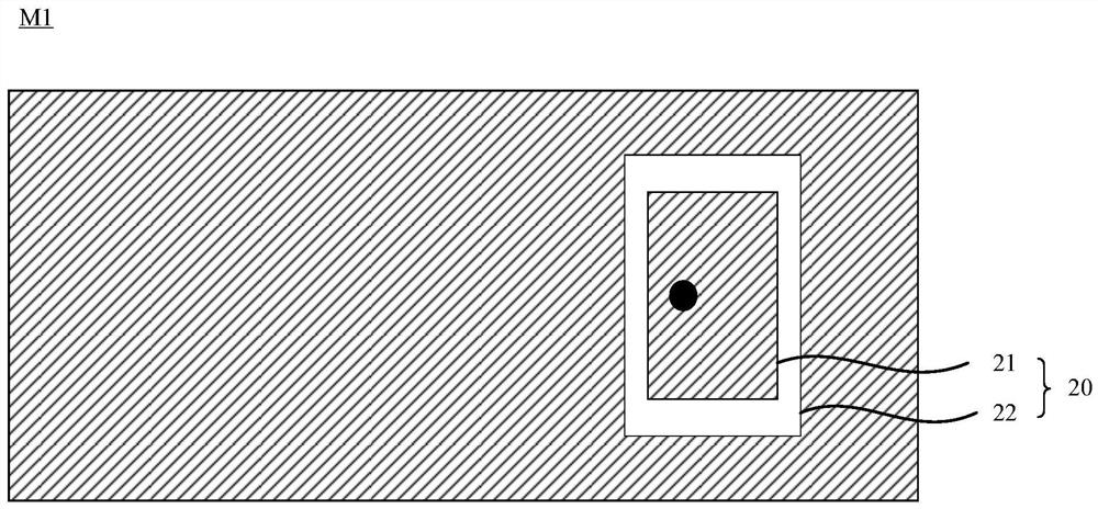
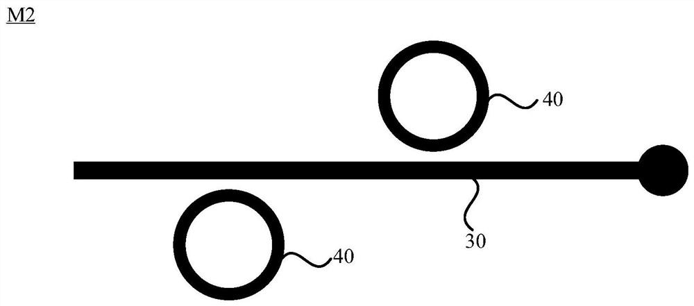
[0074] figure 1 It is a schematic diagram of the film layer structure of a packaged antenna for testing the complex dielectric constant provided by the embodiment of the present application. figure 2 yes figure 1 Schematic diagram of the structure of the middle antenna layer, image 3 yes figure 1 Schematic diagram of the structure of the middle layer, such as figure 1 , figure 2 and image 3 As shown, the packaged antenna 100 for testing the complex permittivity provided by the embodiment of the present a...


PUM


Abstract

The embodiment of the invention discloses a complex dielectric constant measurement method, a radio frequency device, an integrated circuit and a radio device. An antenna structure for testing the complex permittivity comprises an antenna layer, a dielectric layer and a metal ground layer which are stacked in sequence, a radiation unit which is arranged in the antenna layer; a feeder line which is connected with the radiation unit; a resonance structure which is arranged on the feeder line or close to the feeder line; wherein the radiation unit is used for radiating a radio signal so as to obtain the actually measured resonant frequency of the resonant structure based on the extreme value gain of the radio signal in a preset frequency band range; and obtaining the complex dielectric constant of the dielectric layer based on the actually measured resonant frequency and the extreme value gain. The complex dielectric constant measurement method provided by the embodiment of the invention is simple to operate, visual in effect and relatively high in precision.

Description

technical field [0001] The embodiments of the present application relate to the field of electronic technology, and in particular to a method for measuring complex permittivity, radio frequency devices, integrated circuits and radio devices. Background technique [0002] As an important electromagnetic wave transmission medium, high-frequency media are widely used in the design and development of various high-frequency circuits, antennas and other fields. The electromagnetic parameters of high-frequency dielectric materials generally refer to complex permittivity and complex permeability, usually expressed in the form of complex numbers. In actual antenna design, the complex permittivity is usually measured by two parameters, the permittivity and the loss tangent. Different manufacturers or different batches of microwave dielectrics of the same manufacturer often have different complex dielectric constants, which affect product design, debugging and production. Therefore, ...

Claims


Application Information

Patent Timeline
Patent Type & Authority Applications(China)
IPC IPC(8): H01Q1/38H01Q1/50G01R27/26
Inventor 庄凯杰李珊陈哲凡王典
Owner CALTERAH SEMICON TECH SHANGHAI CO LTD
Learn More