Vacuum system and immersion lithography machine using same
A vacuum system and vacuum source technology, applied in the field of vacuum systems, can solve the problems of high cost, complicated installation and configuration, and many fluid components, and achieve the effects of stable vacuum pressure, reduced complexity and cost
- Summary
- Abstract
- Description
- Claims
- Application Information
AI Technical Summary
Problems solved by technology
Method used
Image

Examples
Embodiment 1
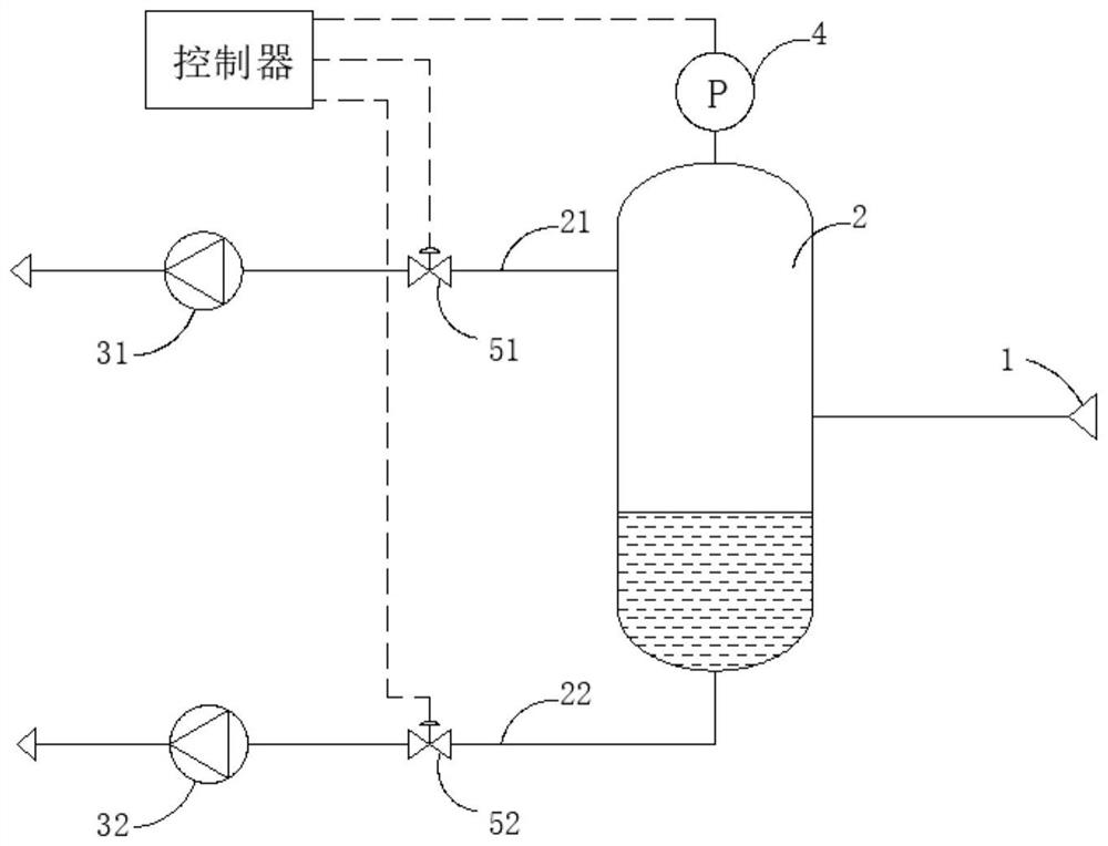
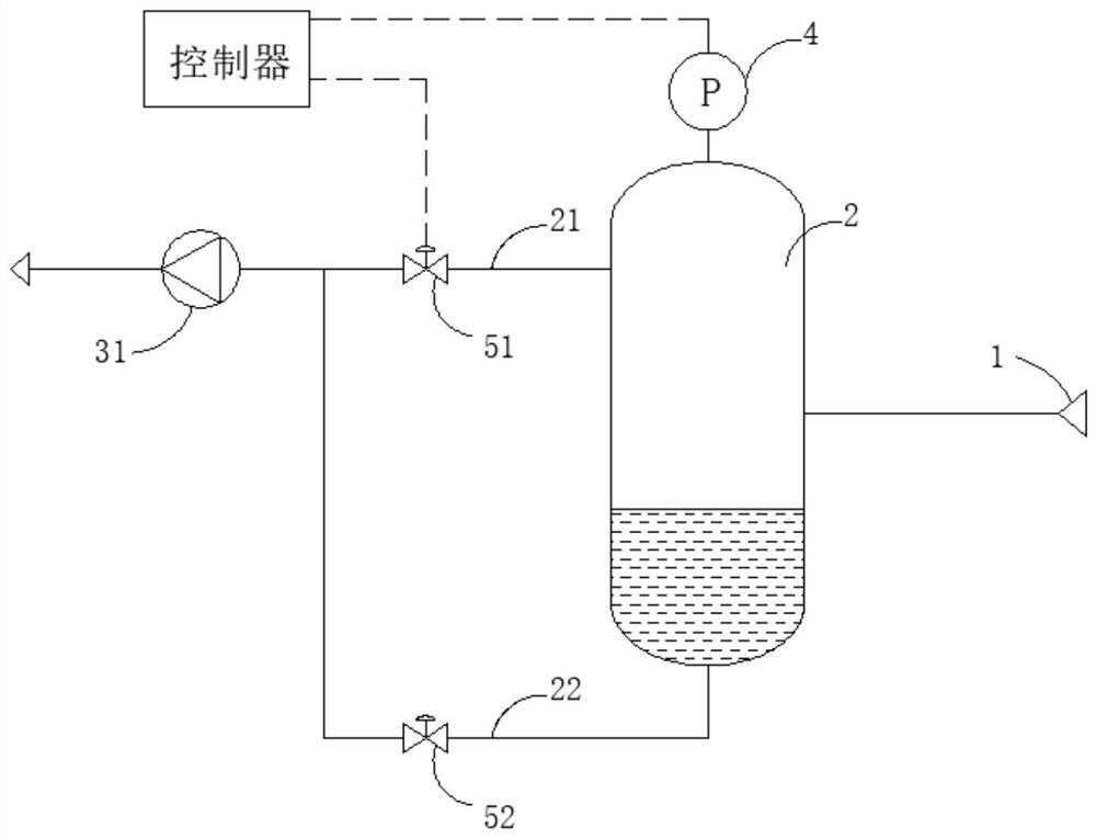
[0025] A vacuum system, comprising a gas-liquid separation tank 2; the upper part of the gas-liquid separation tank 2 leads to a first flow path 21, the lower part of the gas-liquid separation tank 2 leads to a second flow path 22, and the first flow path 21 is provided with a first control valve 51 ; The second control valve 52 is set on the second flow path 22; The gas-liquid two-phase flows from the fluid source 1 into the gas-liquid separation tank 2, relying on the principle of gravity separation, the gas phase gathers in the upper part of the gas-liquid separation tank 2 and the liquid phase gathers in the lower part of the gas-liquid separation tank 2; the gas enters the first flow path 21, the liquid enters the second flow path 22; the gas and liquid are continuously pumped by the first vacuum source 31 after they merge. The pressure sensor 4 is set to monitor the pressure inside the gas-liquid separation tank 2 and transmits the pressure signal to the controller. Adj...
Embodiment 2
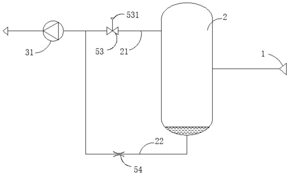
[0029] Such as image 3 As shown, a vacuum regulator 53 is set in the first flow path 21, such as the ITV 2090 series vacuum regulator of SMC brand, and the vacuum regulator 53 can adjust the pressure in the first flow path 21 according to the signal provided by the control source 531 to make it Stable, the control source 531 can be an electrical signal, a gas source, a liquid source or a manual adjustment device; adjusting the pressure in the first flow path 21 to stabilize means controlling the pressure in the gas-liquid separation tank 2 to stabilize. The remaining implementation modes are the same as the first embodiment.
[0030] For the situation that the gas content in the gas-liquid two-phase flow is small, the second flow path 22 can be set as a small elongated tube with an inner diameter; or the control valve in the second flow path 22 can use a throttle 54; the throttle 54 can be a simple damping hole, or a valve that can manually adjust the opening. Through the l...
Embodiment 3
[0032] Such as Figure 4 As shown, the vacuum system also includes a buffer tank 20, the first flow path 21 and the second flow path 22 are connected to the buffer tank 20, and gas and liquid are respectively introduced into the buffer tank 20; preferably the first flow path 21 is connected to the buffer tank 20 the upper part of the buffer tank 20 while the second flow path 22 is connected to the lower part of the buffer tank 20; use the first vacuum source 31 to pump fluid from the bottom of the buffer tank 20. All the other implementations are the same as in Embodiment 2.
[0033] Using the buffer tank 20 as the mixing node of the first flow path 21 and the second flow path 22 effectively expands the volume of the mixing node, can reduce the mutual impact interference between gas and liquid, and is beneficial to suppress the pressure pulsation generated during the fluid mixing process, It is also beneficial to maintain and improve the control accuracy of the vacuum regulat...
PUM
 Abstract
Description
Claims
Application Information
 - R&D
- Intellectual Property
- Life Sciences
- Materials
- Tech Scout
- Unparalleled Data Quality
- Higher Quality Content
- 60% Fewer Hallucinations
Browse by: Latest US Patents, China's latest patents, Technical Efficacy Thesaurus, Application Domain, Technology Topic, Popular Technical Reports.
© 2025 PatSnap. All rights reserved.Legal|Privacy policy|Modern Slavery Act Transparency Statement|Sitemap|About US| Contact US: help@patsnap.com