Annular light source capable of conveniently adjusting light-emitting angle

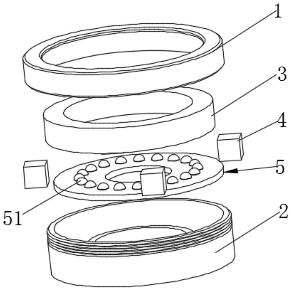
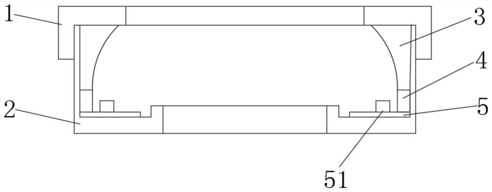
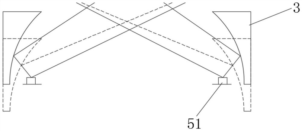
A light-emitting angle, ring-shaped light source technology, applied in the direction of semiconductor devices, light sources, electric light sources, etc. of light-emitting elements, can solve the problems of inability to meet application requirements, increase production and use costs, weak light source compatibility, etc., to meet the needs of industrial rapid detection. , Reduce the effect of different light-emitting angles and easily adjust the light-emitting angle

Pending Publication Date: 2021-04-16
GUANGDONG AOPUTE TECH CO LTD
View PDF0 Cites 1 Cited by
  • Summary
  • Abstract
  • Description
  • Claims
  • Application Information

AI Technical Summary

Problems solved by technology

[0003] At present, the traditional structure of the ring light source on the market is mainly composed of a fixed housing, LED and lamp board PCB. When the object to be tested requires a different luminous inclination angle, it is necessary to manually replace the light source module to achieve the purpose of testing different types of objects. Operation The process is cumbersome; at the same time, the compatibility of the same light source is weak, and it is necessary to design a variety of light source modules to adapt to different types of objects, resulting in waste of design resources, increased production and use costs, and cannot meet the needs of industrial applications.

Method used


Image

  • Annular light source capable of conveniently adjusting light-emitting angle
  • Annular light source capable of conveniently adjusting light-emitting angle
  • Annular light source capable of conveniently adjusting light-emitting angle

Examples


Embodiment Construction

[0022] In the description of the present invention, unless otherwise clearly specified and limited, the terms "first", "second", and "third" are only used for the purpose of description, and cannot be understood as indicating or implying relative importance; "Multiple" refers to two or more; unless otherwise specified or stated, the terms "connected" and "fixed" should be interpreted in a broad sense, for example, "connected" can be fixed or detachable Connected, or integrally connected, or electrically connected; "connected" can be directly connected or indirectly connected through an intermediary. Those of ordinary skill in the art can understand the specific meanings of the above terms in this application according to specific situations.

[0023] In the description of the present invention, it should be understood that the orientation or positional relationship indicated by the terms "upper", "lower", "front", "rear", "left", "right", horizontal" etc. are based on the draw...


PUM


Abstract

The invention belongs to the technical field of machine vision detection, and particularly discloses an annular light source capable of conveniently adjusting a light-emitting angle. The annular light source comprises a first shell, a second shell, a reflecting lens, an adjusting mechanism and a light source. The reflecting lens, the adjusting mechanism and the light source are arranged in an accommodating cavity formed by the first shell and the second shell, and the first shell is movably connected with the second shell; the adjusting mechanism is used for adjusting the axial distance between the reflecting lens and the light source. According to the annular light source capable of conveniently adjusting the light-emitting angle, the light-emitting angle can be conveniently adjusted according to the requirement of the actual light effect, and the problems that annular light sources are multiple in type and not uniform in structure are solved; and the problem that a lamp panel PCB needs to be redesigned due to different light-emitting angles is effectively reduced.

Description

technical field [0001] The invention belongs to the technical field of machine vision detection, and in particular relates to a ring light source which can conveniently adjust the light emitting angle. Background technique [0002] The ring light source is one of the series of light sources commonly used in machine vision. It is a ring light source form that emits light at a certain oblique angle after the LED array is conical, and illuminates a small piece of light through diffuse reflection on the surface of the object to be tested. The light source in the area can highlight the changes of the edge and height of the measured object, and highlight the details that were originally difficult to see. It is widely used in edge detection, lettering on metal surfaces, and damage detection. [0003] At present, the traditional structure of the ring light source on the market is mainly composed of a fixed housing, LED and lamp board PCB. When the object to be tested requires a diff...

Claims


Application Information

Patent Timeline
Patent Type & Authority Applications(China)
IPC IPC(8): F21S2/00F21V7/00F21V15/01F21V14/04F21Y115/10
Inventor 欧青云
Owner GUANGDONG AOPUTE TECH CO LTD
Why Eureka
Try Eureka