Composite insulator defect detection equipment and method, and unmanned aerial vehicle
A composite insulator and defect detection technology, applied in the field of detection, can solve problems that threaten the safe operation of the power grid, and achieve the effect of improving the speed of defect detection
- Summary
- Abstract
- Description
- Claims
- Application Information
AI Technical Summary
Problems solved by technology
Method used
Image
Examples
Embodiment 1
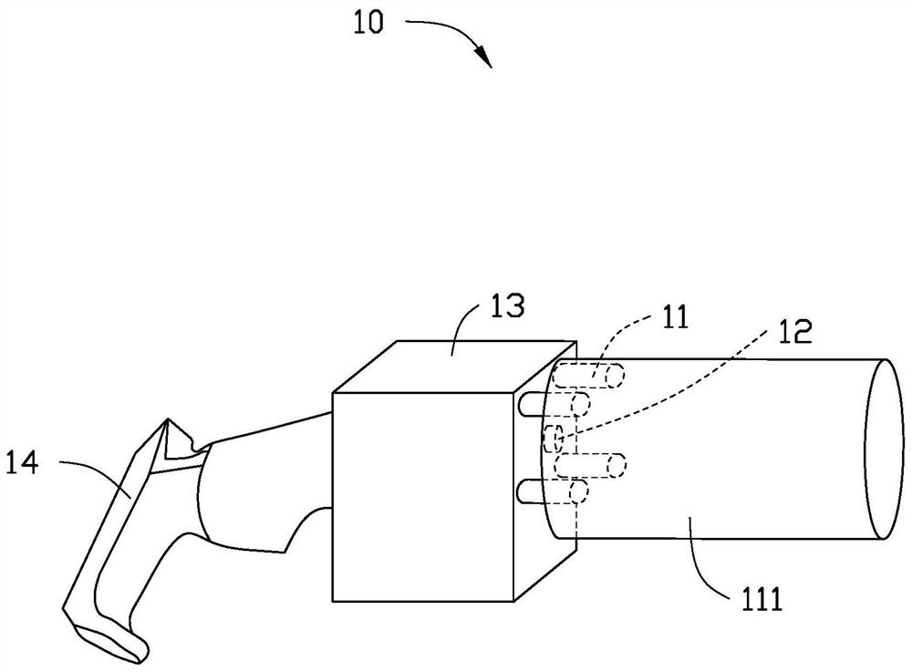
[0020] refer to figure 1 , figure 1 It is a schematic diagram of the composite insulator defect detection device 10 provided in the first embodiment. The composite insulator defect detection equipment 10 includes a microwave emitting device 11 , an infrared imaging device 12 , a detection device 13 and a handle 14 . The infrared imaging device 12 is electrically connected to the detection device 13 . The microwave emitting device 11 and the infrared imaging device 12 are disposed on one side of the detection device 13 , and the handle 14 is disposed on the other side of the detection device 13 .
[0021] The microwave transmitting device 11 is used for transmitting microwave signals to the composite insulator.
[0022] In this embodiment of the application, the term "microwave" refers to electromagnetic waves with a frequency range of 300MHz-300GHz, and their propagation in a medium usually involves processes such as transmission, scattering, and reflection. When microwave...
Embodiment 2
[0053] refer to image 3 , image 3 It is a flow chart of the composite insulator defect detection method according to the second embodiment of the present application. The composite insulator defect detection method comprises the following steps:
[0054] S31, transmitting a microwave signal to the composite insulator.
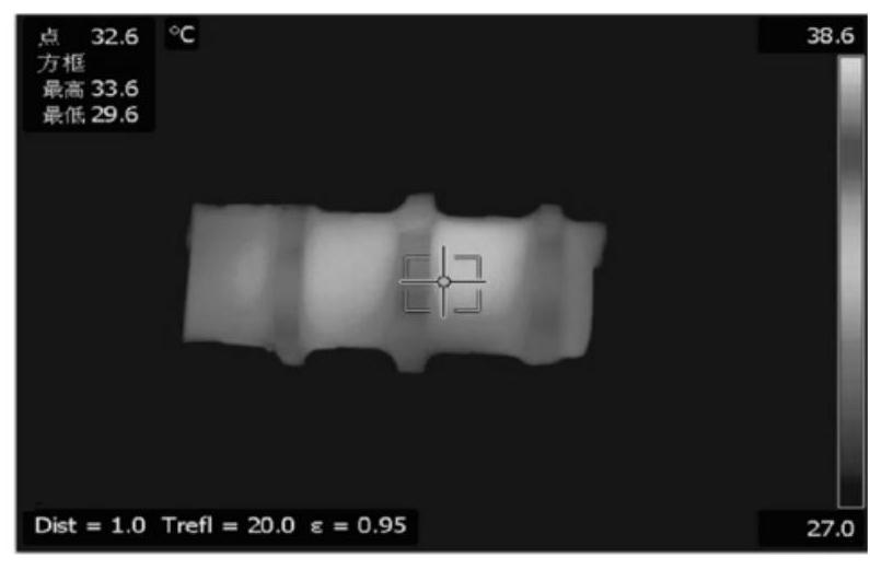
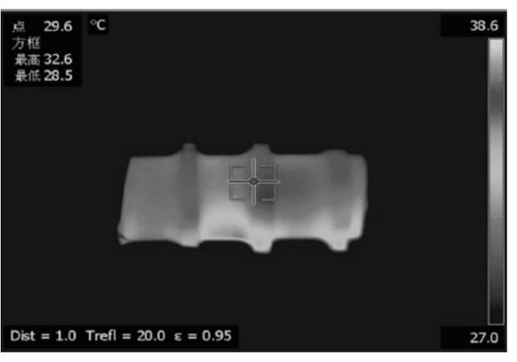
[0055] The microwave signal can cause an obvious temperature rise at the decayed defect part of the composite insulator, while the temperature rise at the normal part is small. The temperature difference between the decayed defect part and the normal part is significant, thus ensuring the accuracy of the test result.
[0056] It can be understood that, in the embodiment of the present application, the microwave signal may be transmitted through a microwave oven or a microwave transmitter.
[0057] S32. Acquire an infrared heat distribution image of the composite insulator.
[0058] It can be understood that, in this embodiment of the present application,...
Embodiment 3
[0065] refer to Figure 4 , Figure 4 A schematic structural diagram of the drone 40 provided in Embodiment 3 of the present application. The drone 40 includes a microwave emitting device 11 , an infrared imaging device 12 and a processor 41 . The processor 41 , the microwave emitting device 11 and the infrared imaging device 12 together constitute the composite insulator defect detection device 10 as described in the first embodiment.
[0066] In the embodiment of the present application, by miniaturizing the transmitting head of the microwave transmitting device 11, the microwave signal emitted by the microwave transmitting device 11 is focused on a small area, and the microwave output of the microwave transmitting device 11 is adjusted. Power, so that the microwave power scattered to the ground meets safety standards.
[0067] It should be noted that the specific implementation manner in the first embodiment may also be applicable to the second and third embodiments.
PUM
 Abstract
Description
Claims
Application Information
 - R&D Engineer
- R&D Manager
- IP Professional
- Industry Leading Data Capabilities
- Powerful AI technology
- Patent DNA Extraction
Browse by: Latest US Patents, China's latest patents, Technical Efficacy Thesaurus, Application Domain, Technology Topic, Popular Technical Reports.
© 2024 PatSnap. All rights reserved.Legal|Privacy policy|Modern Slavery Act Transparency Statement|Sitemap|About US| Contact US: help@patsnap.com


