
Power transmission line fault monitoring method

A fault monitoring and transmission line technology, applied in the fault location, detecting faults by conductor type, measuring electricity, etc., can solve the problems of reducing fault maintenance efficiency, wire whiplash damage, and large wire stress.

Pending Publication Date: 2021-04-09
中达安股份有限公司
View PDF0 Cites 2 Cited by
  • Summary
  • Abstract
  • Description
  • Claims
  • Application Information

AI Technical Summary

Problems solved by technology

[0003] During the use of transmission lines, external factors often cause the sag of the transmission line to deviate too much from the target value, causing the transmission line to fail; if the sag value is too small, the stress of the tensioned wire is large; Will be forced to further elongate or even break
Especially under the weather conditions of rain and snow disasters in the south, the tower is prone to lodging risk: if the sag value is too large, the safety distance to the object to be crossed is insufficient, and the conductor will be damaged due to multiple factors such as continuous overvoltage of the system, high temperature and heavy load. Self-swaying, resulting in discharge between the wires and between the wires relative to the tower; under severe weather conditions such as strong winds and typhoons, the wires will swing beyond their allowable range, causing the wires to whip each other and damage the wires connected to the tower.
[0004] After the failure of the transmission line, it is difficult to accurately determine whether the transmission line failure is caused by damage and broken strands, which often leads to misjudgment, which affects subsequent maintenance and greatly reduces the efficiency of fault maintenance

Method used


Image

  • Power transmission line fault monitoring method
  • Power transmission line fault monitoring method

Examples


Embodiment Construction

[0028] Below in conjunction with accompanying drawing and embodiment the present invention will be further described:

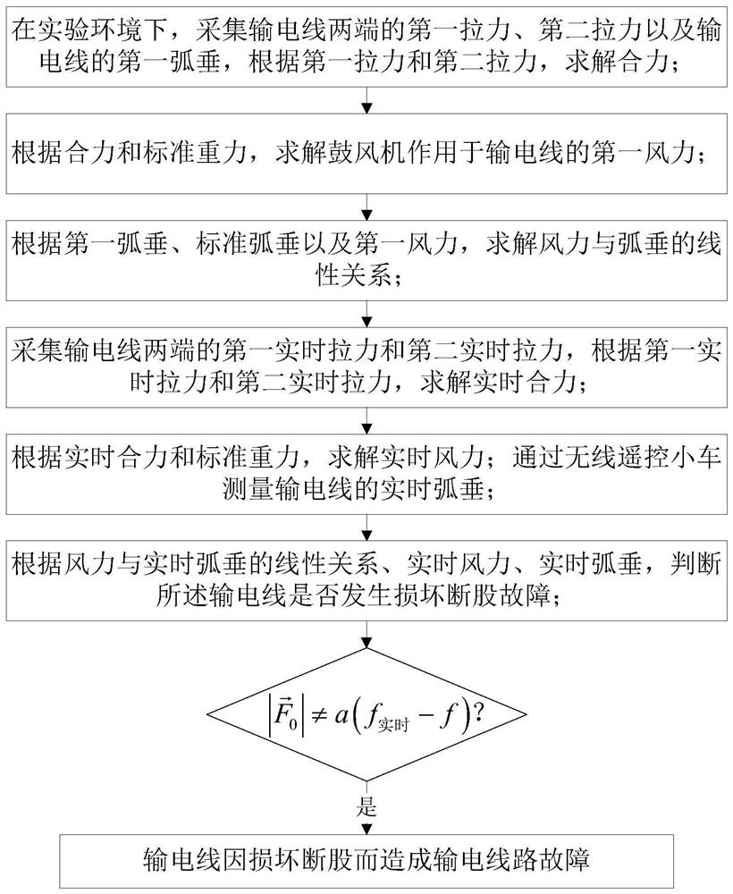
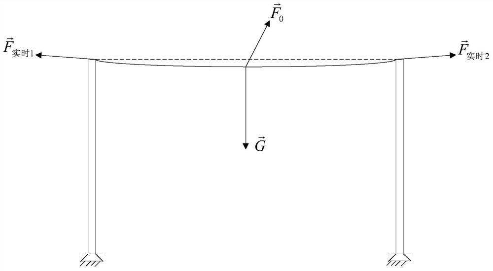
[0029] Such as Figure 1-2 As shown, in a specific embodiment of the present invention, a transmission line fault monitoring method, the method includes the following steps:

[0030] Step S1, in the experimental environment, collect the first tension at both ends of the transmission line second pull and the first sag f of the transmission line 1 , according to the first pulling force and the second pull Solve the resultant force in, The experimental environment is: under the condition that there is no influence of natural environmental factors, the blower is used to blow the transmission line through a blower, and the natural environmental factors include: wind, rain and snow, etc.; the first sag f 1 Measured by a wireless remote control car; the two ends of the transmission line are respectively erected on the first transmission tower and the seco...


PUM


Abstract

The invention discloses a power transmission line fault monitoring method. The method comprises the following steps: collecting a first tension and a second tension at two ends of a power transmission line and a first sag of the power transmission line in an experimental environment, and solving a resultant force according to the first tension and the second tension; solving the first wind power according to the resultant force and the standard gravity; solving a linear relation between the wind power and the sag; solving a real-time resultant force according to the first real-time tension and the second real-time tension; solving real-time wind power according to the real-time resultant force and the standard gravity; and according to the linear relationship between the wind power and the real-time sag, the real-time wind power and the real-time sag, judging whether the power transmission line has a power transmission line fault caused by damage and strand breakage. According to the invention, when the power transmission line breaks down, whether the power transmission line breaks down due to damage and strand breakage can be effectively judged, the fault of the power transmission line can be accurately judged, the fault judgment time is effectively saved, and the fault maintenance efficiency is effectively improved.

Description

technical field [0001] The invention relates to the technical field of power transmission lines, in particular to a fault monitoring method for power transmission lines. Background technique [0002] Overhead transmission lines are the main artery of the power industry and an important part of the power system. The transmission line conductor sags between adjacent towers to form an arc curve, and the sag is called sag. The size of the sag is related to the span, height difference, wire length, wire weight, and stress on the wire. Natural factors such as temperature, wind, ice and snow also affect it. It is an important process to ensure the construction quality to accurately observe the sag of the overhead transmission line and guide the line tightening operation until the target sag is achieved. [0003] During the use of transmission lines, external factors often cause the sag of the transmission line to deviate too much from the target value, causing the transmission li...

Claims


Application Information

Patent Timeline
IPC IPC(8): G01R31/08
CPCG01R31/085G01R31/088
Inventor 洪少智吴生清陈家天
Owner 中达安股份有限公司
Learn More