
Composite spiral stirrup confined concrete shear wall structure and construction method thereof

A technology of confining concrete and spiral stirrups, which is applied to structural elements, walls, building components, etc., can solve the problems that core concrete cannot play an effective confinement role, large cracks in shear walls, and insufficient wall confinement, etc., so as to save steel bars dosage, reduce harmful gas emissions, and enhance the effect of restraint

Pending Publication Date: 2021-04-09
XI'AN UNIVERSITY OF ARCHITECTURE AND TECHNOLOGY
View PDF0 Cites 0 Cited by
  • Summary
  • Abstract
  • Description
  • Claims
  • Application Information

AI Technical Summary

Problems solved by technology

[0004] Aiming at the technical problems existing in the prior art, the object of the present invention is to provide a composite spiral stirrup restrained concrete shear wall structure and its construction method, to solve the existing problem of disposing spiral stirrups in high-strength concrete shear walls The core concrete cannot be effectively constrained, the wall is not constrained enough, and the technical problems of large cracks in the shear wall and bottom collapse are prone to occur

Method used


Image

  • Composite spiral stirrup confined concrete shear wall structure and construction method thereof
  • Composite spiral stirrup confined concrete shear wall structure and construction method thereof
  • Composite spiral stirrup confined concrete shear wall structure and construction method thereof

Examples


Embodiment Construction

[0032] The technical solutions of the embodiments of the present invention will be explained and described below in conjunction with the accompanying drawings of the embodiments of the present invention, but the following embodiments are only preferred embodiments of the present invention, not all of them. Based on the examples in the implementation manners, other examples obtained by those skilled in the art without making creative efforts all belong to the protection scope of the present invention.

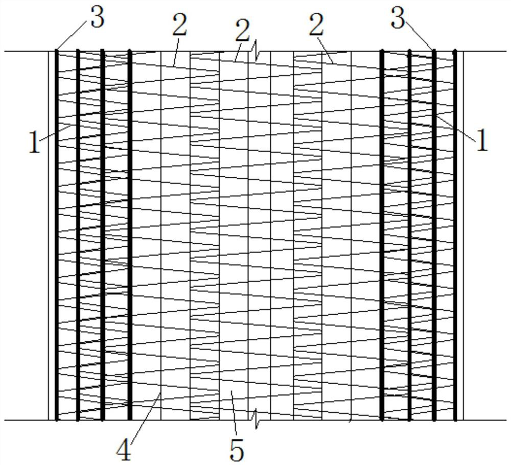
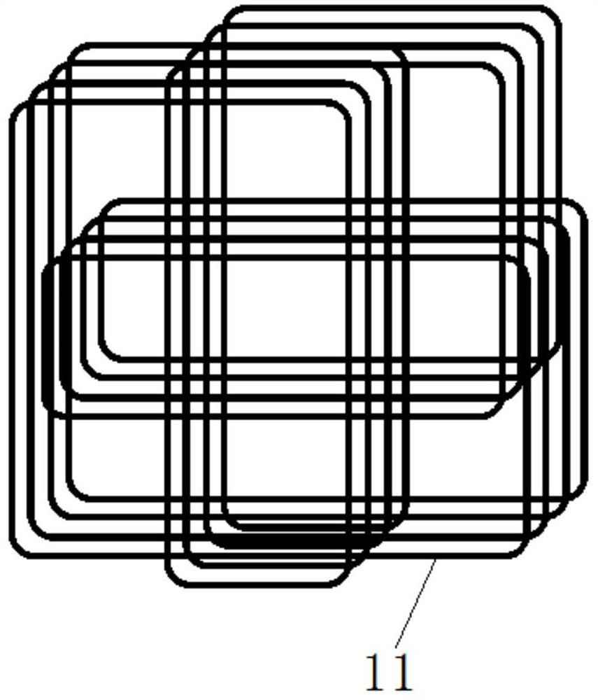
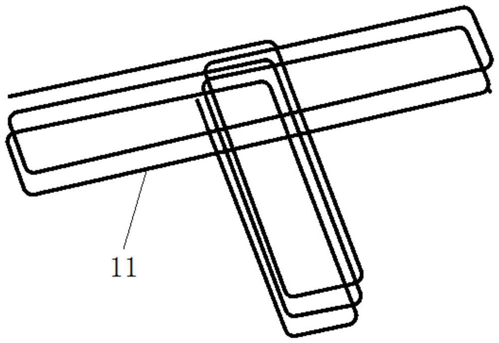
[0033] as attached Figure 1-5 As shown, the present invention provides a composite spiral stirrup restraint concrete shear wall structure, comprising continuous composite spiral stirrup 1, continuous composite spiral horizontal distribution reinforcement 2, longitudinal reinforcement 3, vertical distribution reinforcement 4 and concrete 5; The composite spiral horizontally distributed ribs 2 are evenly distributed in the concrete 5, and the continuous composite spiral horizonta...


PUM

PropertyMeasurementUnit
diameteraaaaaaaaaa
strengthaaaaaaaaaa

Abstract

The invention discloses a composite spiral stirrup confined concrete shear wall structure and a construction method thereof. The composite spiral stirrup confined concrete shear wall structure comprises continuous composite spiral stirrups, wherein continuous composite spiral horizontal distribution bars are evenly distributed in concrete; on the same horizontal plane, the adjacent continuous composite spiral horizontal distribution bars are fixedly connected together; the continuous composite spiral stirrups are symmetrically arranged at the positions of confined edge components at the two ends of the concrete; and longitudinal bars are evenly arranged in the overlapping areas of the continuous composite spiral stirrups and the continuous composite spiral horizontal distribution bars, and vertical distribution bars are evenly arranged in the continuous composite spiral horizontal distribution bars. According to the composite spiral stirrup confined concrete shear wall structure and the construction method thereof, the continuous composite spiral stirrups are arranged on the edge of a wall, core concrete can be effectively confined, the effective confined area of the concrete is increased, and the compressive strength and the ultimate compressive strain of the concrete are improved; and a stable steel reinforcement framework is formed by the continuous composite spiral horizontal distribution bars and the vertical distribution bars, the overall stability of the wall is enhanced, transverse deformation of the wall concrete is confined, and the anti-seismic property of the wall is improved.

Description

technical field [0001] The invention relates to the technical field of shear wall structures, in particular to a concrete shear wall structure constrained by composite spiral stirrups and a construction method thereof. Background technique [0002] The shear wall at the bottom of the high-rise structure bears large axial force, bending moment and shear force. Under the action of a strong earthquake, the shear wall with a high axial compression ratio is prone to compressive shear or crush failure, which makes its component strength It is difficult to repair after the earthquake; how to improve the seismic performance of the shear wall is one of the key issues in the seismic design of high-rise structures. [0003] At present, in order to solve the above problems, high-strength concrete materials are often used, and spiral stirrups are arranged in the shear walls to form a spiral stirrup-constrained concrete shear wall structure system; but high-strength concrete itself is bri...

Claims


Application Information

Patent Timeline
Patent Type & Authority Applications(China)
IPC IPC(8): E04B2/56E04C5/06
CPCE04B2/56E04C5/064
Inventor 赵花静姜维山赵珺
Owner XI'AN UNIVERSITY OF ARCHITECTURE AND TECHNOLOGY
Learn More