Automobile part punching device
A punching device, auto parts technology, applied in the direction of maintenance and safety parts, boring/drilling, drilling/drilling equipment, etc., can solve the problems of surface damage, large pulling force, flanging and other problems of parts, and achieve guarantee The effect of sustainable work
- Summary
- Abstract
- Description
- Claims
- Application Information
AI Technical Summary
Problems solved by technology
Method used
Image
Examples
Embodiment 1
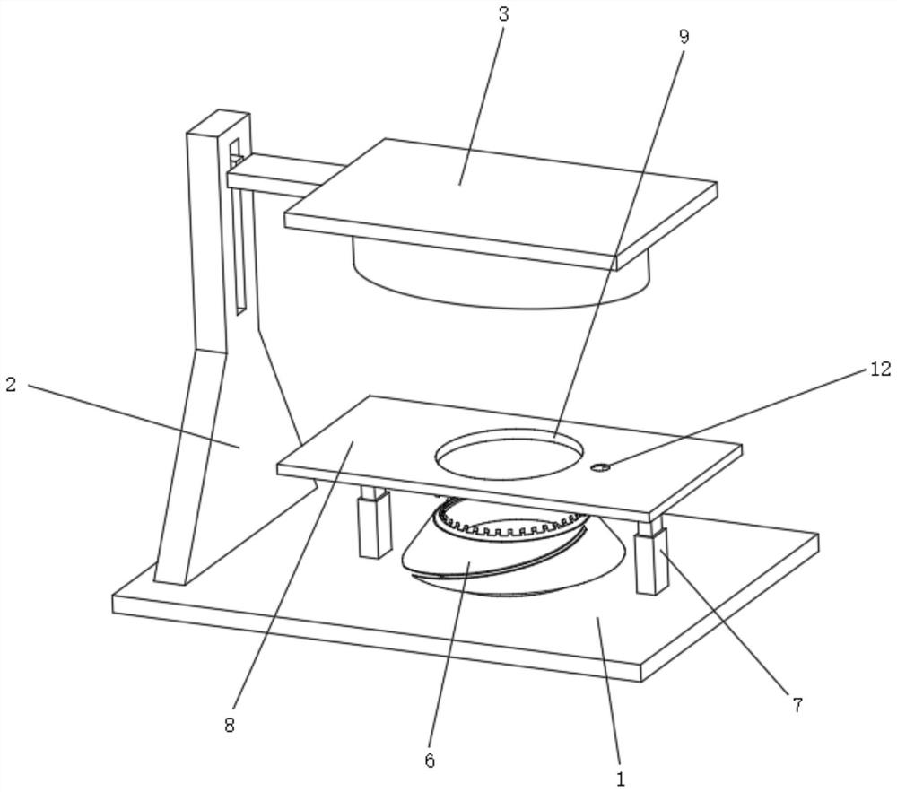
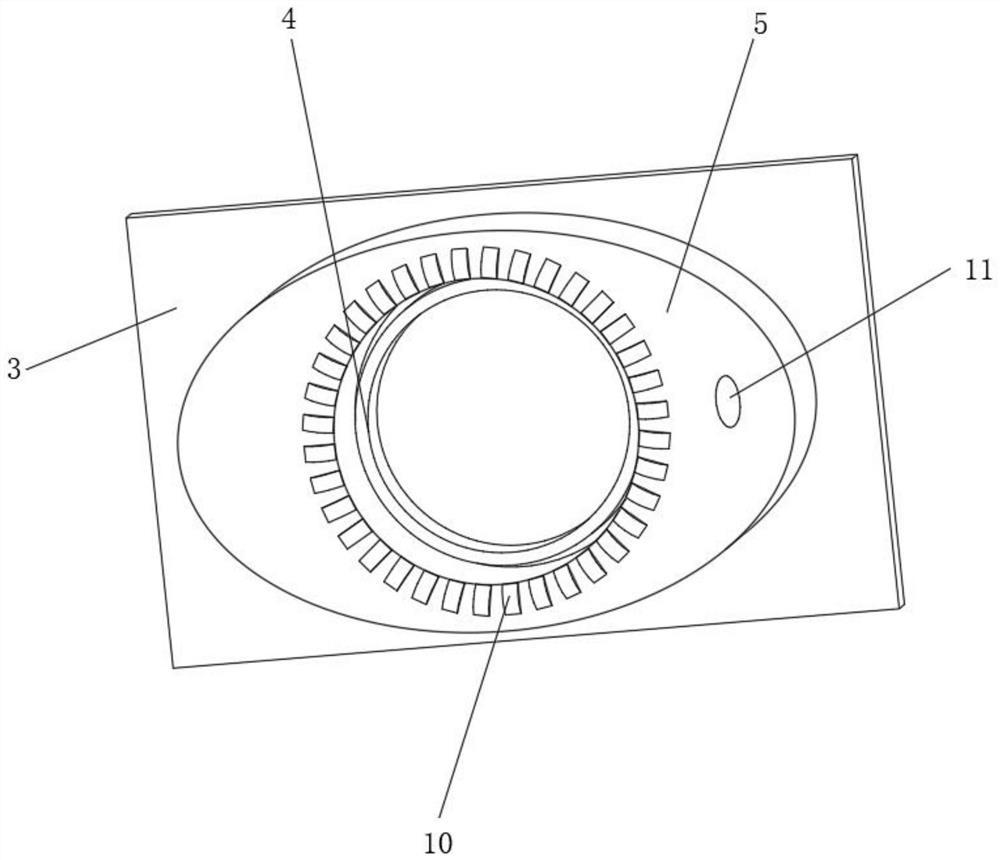
[0038] like Figure 1-3 As shown, the present invention provides a technical solution: a punching device for auto parts, including a punching support plate 1, the left side of the top of the punching support plate 1 is fixedly connected with a travel drive 2, and the output end of the travel drive 2 is fixedly connected There is a punching platen 3, the middle position of the bottom of the punching platen 3 is rotatably connected with a screw-in tool mechanism 4, the bottom of the punching platen 3 and outside the screw-in tool mechanism 4 is fixedly connected with a stable air bag 5, and a punching support plate 1 The middle position of the top is fixedly connected with an auxiliary circumcision mechanism 6, and the top of the perforated support plate 1 is fixed and is fixedly connected with an elastic telescopic rod 7 on both sides of the auxiliary circumcision mechanism 6, and the elastic telescopic rod 7 is far away from the perforated support plate One end of 1 is fixedly...
Embodiment 2
[0044] like Figure 4-6 As shown, on the basis of Embodiment 1, the present invention provides a technical solution: a punching device for auto parts, the screw-in tool mechanism 4 includes a drive limit frame 41, and the top end of the drive limit frame 41 is fixed to the punching platen 3 Connecting, the bottom end inside the drive limiting frame 41 is penetrated and rotatably connected with a transmission drive shaft 42 , and one end of the transmission drive shaft 42 outside the drive limiting frame 41 is fixedly connected with a perforated tooth tube 43 .
[0045] The right side of the drive limiting frame 41 is connected with a conduction tube 45 , and one end of the conduction tube 45 inside the drive limiter frame 41 is fixedly connected with a contact sealing port 46 .
[0046] The outer surface of the transmission drive shaft 42 is uniformly and fixedly connected with a sealing transmission plate 47 . The sealing transmission plate 47 is arranged corresponding to the...
Embodiment 3
[0049] like Figure 7 As shown, on the basis of Embodiment 1 and Embodiment 2, the present invention provides a technical solution: a kind of auto parts punching device, the auxiliary ring cutting mechanism 6 includes a ring cutting blade 61, and the vertical ring cutting blade 61 outside The position is slidably connected with a driving ring piece 62 , and the top surface of the driving ring piece 62 is evenly and fixedly connected with an auxiliary cutting tooth 63 , which is arranged corresponding to the tooth surface of the perforated tooth tube 43 . By converting the extrusion force into a rotation force, the bottom surface of the fitting is initially scored to achieve the purpose of pre-processing.
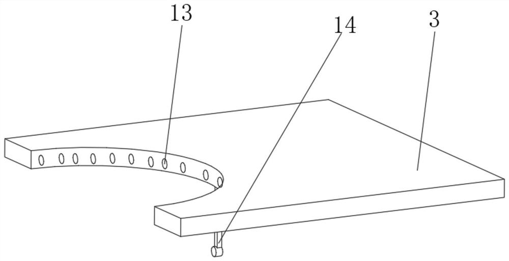
[0050] The outer surface of the driving ring piece 62 is provided with a driving thread groove 64 , and the driving thread groove 64 is arranged corresponding to the pressing travel wheel 14 . The fitting is cut along the score to allow the fitting to be punched from the bo...
PUM
 Abstract
Description
Claims
Application Information
 - R&D
- Intellectual Property
- Life Sciences
- Materials
- Tech Scout
- Unparalleled Data Quality
- Higher Quality Content
- 60% Fewer Hallucinations
Browse by: Latest US Patents, China's latest patents, Technical Efficacy Thesaurus, Application Domain, Technology Topic, Popular Technical Reports.
© 2025 PatSnap. All rights reserved.Legal|Privacy policy|Modern Slavery Act Transparency Statement|Sitemap|About US| Contact US: help@patsnap.com


