
Direct methanol fuel cell catalyst layer gradient membrane electrode and preparation method thereof

A methanol fuel cell and catalytic layer technology, applied in fuel cells, battery electrodes, electrochemical generators, etc., can solve problems such as hindering heat dissipation, fuel and gas transmission, non-uniform distribution of current density, battery aging, etc., to improve concentration The effect of uneven distribution, high water and heat management capacity, and improved utilization

Inactive Publication Date: 2021-04-06
泰州市海创新能源研究院有限公司
View PDF4 Cites 3 Cited by
  • Summary
  • Abstract
  • Description
  • Claims
  • Application Information

AI Technical Summary

Problems solved by technology

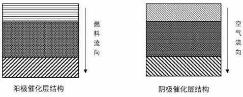
However, due to the liquid water generated during the electrochemical reaction and the accumulation of heat along the direction of gas flow, the catalytic layer near the electrode outlet becomes hotter and less porous, hindering heat dissipation and the transport of fuel and gas, while Since the concentration of reactants and the intensity of the reaction are different in each part of the catalytic layer, the current density in the catalytic layer is not uniformly distributed, and the local high current density will easily lead to accelerated battery aging.

Method used


Image

  • Direct methanol fuel cell catalyst layer gradient membrane electrode and preparation method thereof
  • Direct methanol fuel cell catalyst layer gradient membrane electrode and preparation method thereof
  • Direct methanol fuel cell catalyst layer gradient membrane electrode and preparation method thereof

Examples


Embodiment 1

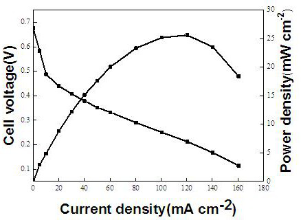
[0041] According to the above steps, the gradient electrode and the membrane electrode of the catalytic layer of the direct methanol fuel cell were prepared, and the discharge test was carried out. The main steps are as follows:

[0042] (1) Preparation of electrodes

[0043] Carbon paper containing polytetrafluoroethylene (PTFE) is used as a diffusion layer, and a microporous layer containing PTFE is coated on the hydrophobic diffusion layer, wherein the content of polytetrafluoroethylene is 15wt.%. Prepare the appropriate proportion of catalyst slurry, using isopropanol as solvent. Use PtRu / C as a catalyst on the anode side and Pt / C as a catalyst on the cathode side, and spray coating on the microporous layer in gradient to form a catalyst layer.

[0044] (2) Treatment of proton exchange membrane

[0045] The membrane was exposed to 5wt.% H 2 o 2 Boil in solution for 1 hour, then wash in deionized water, then boil in 0.5M sulfuric acid solution for 1 hour, and finally boi...

Embodiment 2

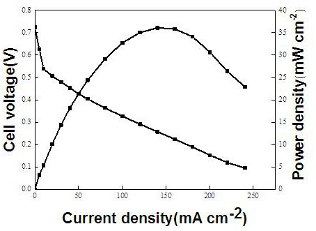
[0053] The direct methanol fuel cell catalytic layer graded membrane electrode of the present invention is tested under the condition of high temperature and dry oxygen. Firstly, a gradient electrode with catalytic layer was prepared according to the same procedure as in Example 1, and a single cell was assembled for discharge test.

[0054] The test conditions are: battery operating temperature 60°C, normal pressure, anode fuel is 1M methanol (flow 2ml min-1), cathode air intake is dry oxygen (flow 199ml min -1 ). The limiting current density can reach 240.32mA cm -2 , the maximum power density reaches 36.10mW cm -2 , Example 2 increased by 37.84% compared to Comparative Example 2.


PUM


Abstract

The invention discloses a direct methanol fuel cell catalyst layer gradient membrane electrode, which comprises a gas diffusion layer, a microporous layer, a catalyst layer and a proton exchange membrane, and is characterized in that the catalyst layer of the direct methanol fuel cell membrane electrode has a spanwise gradient structure, and the catalyst load from the vicinity of a fuel and air inlet to the vicinity of an outlet is gradually increased. Compared with the prior art, the membrane electrode has the advantages that the hydrothermal management capacity is high; the current density is uniformly distributed; and catalyst utilization is improved. In conclusion, the gradient membrane electrode of the catalyst layer of the direct methanol fuel cell is reasonable in structure, powerful in function and suitable for popularization and application.

Description

technical field [0001] The invention relates to the technical field of fuel cells, in particular to a gradient membrane electrode of a direct methanol fuel cell catalyst layer and a preparation method thereof. Background technique [0002] A fuel cell is an energy conversion device that directly converts chemical energy stored in fuel into electrical energy. Because it does not need to go through the Carnot cycle, it has high energy density and energy conversion efficiency. It is a new type of green energy technology. In recent years, due to innovative breakthroughs in fuel cell (Fuel Cell) technology, coupled with multiple pressures such as environmental protection issues and energy shortages, governments of various countries and industries such as automobiles, electric power, and energy have gradually attached importance to the development of fuel cell technology. Fuel cells use alcohol, natural gas, hydrogen, and other fuels to convert them into electricity, so that they ...

Claims


Application Information

Patent Timeline
Patent Type & Authority Applications(China)
IPC IPC(8): H01M8/1004H01M4/86H01M4/88H01M8/1011
CPCH01M8/1004H01M4/8636H01M4/8807H01M4/8817H01M4/8828H01M4/8882H01M8/1011Y02E60/50
Inventor 徐谦常志新朱亚明苏华能马强张玮琦
Owner 泰州市海创新能源研究院有限公司
Learn More