Fabricated bridge substructure and construction method thereof

A prefabricated and bridge technology, applied in the direction of erecting/assembling bridges, bridges, bridge parts, etc., can solve the problems of great impact on urban traffic, difficult to control the appearance quality, heavy weight of prefabricated piers, etc., to shorten the construction period and weight. The effect of light and reduced investment

Pending Publication Date: 2021-04-06
SICHUAN JIAOTOU CONSTR ENG CO LTD
View PDF9 Cites 2 Cited by
  • Summary
  • Abstract
  • Description
  • Claims
  • Application Information

AI Technical Summary

Problems solved by technology

[0003] At present, there are two main methods of bridge construction. One is the traditional cast-in-place method, which is mainly based on artificial binding of steel bars and on-site pouring of concrete. It has high safety performance and good integrity, but a large number of support formworks are required for each step of construction. , the appearance quality is not easy to control and the construction period is long, which has a great impact on urban traffic; the second is the prefabricated assembly type, where concrete beams, slabs, columns and other components are poured and produced in the factory, and then transported to the project site for assembly. The shape is beautiful, but when connecting the various parts of the pier, due to the excessive weight of the existing prefabricated pier column, it needs unconventional large-scale equipment for lifting, and the construction is difficult

Method used


Image

  • Fabricated bridge substructure and construction method thereof
  • Fabricated bridge substructure and construction method thereof
  • Fabricated bridge substructure and construction method thereof

Examples


Embodiment 1

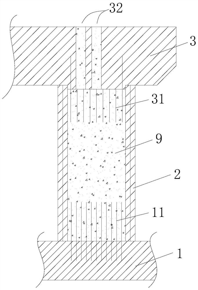
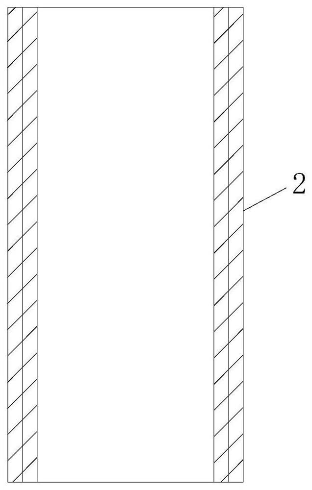
[0057] Such as Figure 1 to Figure 4 As shown, the present invention provides a prefabricated bridge substructure, comprising: a base structure 1, the top of the base structure 1 is annularly arranged with a number of reserved vertical ribs 11 protruding from the top surface of the base structure 1; prefabricated cover beams 3, prefabricated The lower side of the cover beam 3 is circularly arranged with several reserved vertical ribs 31 protruding downwards from the bottom surface of the prefabricated cover beam 3; in the coverage area of ​​the reserved vertical ribs 31 of the cover beam, there is at least one vertically penetrating prefabricated cover beam 3; the base structure 1 and the prefabricated cover beam 3 are connected through the standard prefabricated pier unit 2; the standard prefabricated pier unit 2 is a hollow cylinder with upper and lower openings, and the standard prefabricated pier unit 2 is vertically inserted into the On the top of structure 1, the vertica...

Embodiment 2

[0060] Further, such as Figure 5 to Figure 7 As shown, the standard prefabricated pier column unit 2 can be improved on the basis of Embodiment 1. In this embodiment, the lower inner wall ring of the standard prefabricated pier column unit 2 is provided with several downwardly extending lower end vertical ribs 22 , the vertical rib 22 at the lower end is connected to the main reinforcement of the prefabricated part of the standard prefabricated pier column unit 2 and is bent inward and downward to extend downwards, and can extend downwards to be flush with the lower end surface of the standard prefabricated pier column unit 2. When the standard prefabricated pier column unit 2 When the unit 2 is vertically inserted on the top of the foundation structure 1, the reserved vertical ribs 11 of the foundation can be inserted into the standard prefabricated pier column unit 2 and correspondingly welded, screwed or bound with the lower vertical ribs 22 to further strengthen the struct...

Embodiment 3

[0066] Further, such as Figure 9 to Figure 11As shown, the standard prefabricated pier column unit 2 can be improved on the basis of the second embodiment. In this embodiment, the first prefabricated pier column 5 further designed on the basis of the standard prefabricated pier column unit 2 is also included. The prefabricated pier column 5 includes a standard prefabricated pier column unit 2 and a plurality of first vertical ribs 51, the plurality of first vertical ribs 51 are integrally formed with the upper end vertical ribs 24 of the standard prefabricated pier column unit 2, and extend upwards out of the standard prefabricated pier The upper end surface of the column unit 2; and the second prefabricated pier column 6 further designed on the basis of the standard prefabricated pier column unit 2, the second prefabricated pier column 6 includes the standard prefabricated pier column unit 2 and some second vertical ribs 61, and some second prefabricated pier columns 61 Two ...


PUM


Abstract

The invention discloses a fabricated bridge substructure which comprises a foundation structure, a prefabricated bent cap and a quasi-prefabricated pier column unit, and foundation reserved vertical ribs are arranged at the top of the foundation structure; cover beam reserved vertical ribs are arranged on the lower side of the prefabricated bent cap. At least one sprue gate vertically penetrating through the prefabricated bent cap is arranged in the area covered by the reserved vertical ribs of the bent cap; a standard prefabricated pier column unit is a hollow cylinder with openings in the upper portion and the lower portion and penetrates through the foundation reserved vertical ribs to be vertically inserted into the top of the foundation structure; the prefabricated bent cap is in lap joint with the top of the standard prefabricated pier column unit and extends into the hollow area of the standard prefabricated pier column unit through the cover beam reserved vertical ribs to be connected in an inserted mode. Expansion concrete is cast in situ in the sprue gate and the hollow area of the standard prefabricated pier column unit. The construction quality can be controlled in a cast-in-place and prefabricating combined mode, investment of formworks is omitted, the weight is low, installation is convenient and rapid, the aerial work time can be effectively shortened, the construction efficiency is improved, and the construction period is shortened.

Description

technical field [0001] The invention relates to the technical field of bridge engineering, in particular to an assembled bridge substructure and a construction method thereof. Background technique [0002] With the continuous advancement of my country's urbanization process, the problem of traffic congestion has become increasingly prominent, and has gradually become a key factor affecting the development of urbanization. As the preferred solution to my country's traffic congestion problem, urban bridges have been widely used in large, medium and small cities in China. [0003] At present, there are two main methods of bridge construction. One is the traditional cast-in-place method, which is mainly based on manual binding of steel bars and on-site pouring of concrete. It has high safety performance and good integrity, but a large number of support formworks are required for each step of construction. , the appearance quality is not easy to control and the construction perio...

Claims


Application Information

Patent Timeline
Patent Type & Authority Applications(China)
IPC IPC(8): E01D19/02E01D21/00E01D19/00
CPCE01D19/02E01D21/00E01D19/00
Inventor 莫志强罗红王元朱倩廖远强代峻儒
Owner SICHUAN JIAOTOU CONSTR ENG CO LTD
Why Eureka
Try Eureka