Neodymium iron boron electroplating device
An electroplating device, NdFeB technology, applied to circuits, electrical components, electrolytic processes, etc., can solve the problems of inconvenient NdFeB electroplating, inconvenient clamping of NdFeB of different shapes, and inability to NdFeB electroplating, etc., to achieve Easy to replace and clean, easy to fix or disassemble, easy to operate
- Summary
- Abstract
- Description
- Claims
- Application Information
AI Technical Summary
Problems solved by technology
Method used
Image

Examples
Embodiment 1
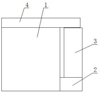
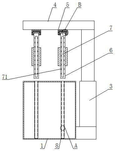
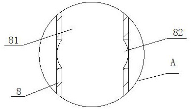
[0029] see figure 1 - Figure 7 As shown, the present invention provides a technical solution: a neodymium-iron-boron electroplating device, including an electroplating box 1, a support seat 2 is fixedly installed on the right side of the electroplating box 1, and a hydraulic cylinder 3 is fixedly installed on the upper end of the support seat 2. The upper end of the cylinder 3 is welded with a top plate 4, the lower end of the top plate 4 is welded with a fixed block 5, the lower end of the fixed block 5 is provided with an electroplating plate 6, the front end of the electroplating plate 6 is provided with an anti-plating plate 7, and the front and rear ends of the electroplating box 1 are uniform. An electroplating fixed seat 8 is welded, and a movable slider 51 is welded on the upper end of the electroplated plate 6. The inside of the movable slider 51 is provided with a bidirectional thrust spring 52, and the left and right sides of the bidirectional thrust spring 52 are ...
Embodiment 2
[0031] see Figure 4 As shown, on the basis of Embodiment 1, the present invention provides a technical solution: the right side of the blocking plate 53 is welded with a limit column 54, the moving slider 51 is arranged in the limit groove 61, and the limit column 54 and the limit The size of the left and right ends of the position groove 61 match, the blocking plate 53 pushes the limit column 54 to move left and right in the limit groove 61 through the two-way thrust spring 52, and the moving slider 51 is fixed in the fixed position by the limit column 54 and the limit groove 61. Inside the block 5, the upper end surface of the push rod 65 is penetrated with a blocking hole, and the sliding hand push plate 64 is movably installed in the inside of the sliding groove 63, and the push rod 65 drives the mounting block 66 through the sliding hand pushing plate 64 to cooperate with the sliding groove 63 in the electroplating process. Move left and right in the clamping circle 62, ...
Embodiment 3
[0033] see figure 2 , Figure 5 and Figure 6 As shown, on the basis of Embodiment 1 and Embodiment 2, the present invention provides a technical solution: the front end of the thrust block 622 is welded with a lower push plate, the inner top of the clamping frame 621 is welded with an elastic spring 623, and the elastic spring 623 The upper end of the lower end of the thrust block 622 is fixedly installed, and the thrust block 622 is movably installed inside the clamping frame 621. The thrust block 622 drives the fixed lock post 624 to move up and down in the blocking hole through the elastic spring 623. , so that it drives the elastic spring 623 to move upward in the clamping frame 621, and makes the fixed lock column 624 move out from the blocking hole, and then slides the hand push plate 64 by moving left or right to make it in the sliding groove 63 Push the push rod 65 to move left or right, and drive the NdFeB clamping arc plate 67 to move left and right in the electr...
PUM
 Abstract
Description
Claims
Application Information
 - R&D
- Intellectual Property
- Life Sciences
- Materials
- Tech Scout
- Unparalleled Data Quality
- Higher Quality Content
- 60% Fewer Hallucinations
Browse by: Latest US Patents, China's latest patents, Technical Efficacy Thesaurus, Application Domain, Technology Topic, Popular Technical Reports.
© 2025 PatSnap. All rights reserved.Legal|Privacy policy|Modern Slavery Act Transparency Statement|Sitemap|About US| Contact US: help@patsnap.com