
Electrical connector having holding pieces with a notch for holding a circuit board

a technology of circuit board and holding piece, applied in the direction of coupling device connection, two-part coupling device, incorrect coupling prevention, etc., can solve the problem that the conventional usb 3.0 type-c connector may become useless, and achieve the effect of facilitating electroplating and enhancing the overall strength of the shell

Active Publication Date: 2017-02-21
ADVANCED CONNECTEK INC
View PDF11 Cites 8 Cited by
  • Summary
  • Abstract
  • Description
  • Claims
  • Application Information

AI Technical Summary

Benefits of technology

The present invention is an electrical connector with holding pieces that can hold a circuit board securely. The connector has a strong shell made through a two-stage drawing process that is easy to plate. The simple process helps produce the connector without any bending or trimming.

Problems solved by technology

The drawback of the conventional USB 3.0 type-C plug is that the pair of holding legs 14 is integrally formed with the shell 12 and is a part of the shell 12.
What is worse is that the conventional USB 3.0 type-C connector may become useless when the pair of holding legs 14 is damaged and fails to clamp the PCB board 16 tightly.

Method used


Image

  • Electrical connector having holding pieces with a notch for holding a circuit board
  • Electrical connector having holding pieces with a notch for holding a circuit board
  • Electrical connector having holding pieces with a notch for holding a circuit board

Examples


Embodiment Construction

[0029]The present invention is to provide an electrical connector having a pair of holding pieces to be assembled with the electrical connector and a shell formed by a two-stage drawing process.

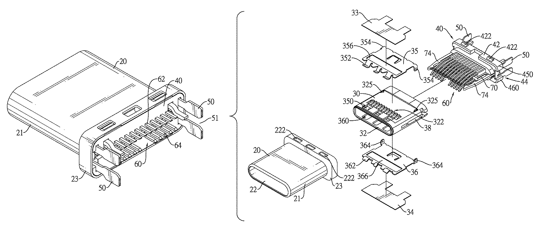
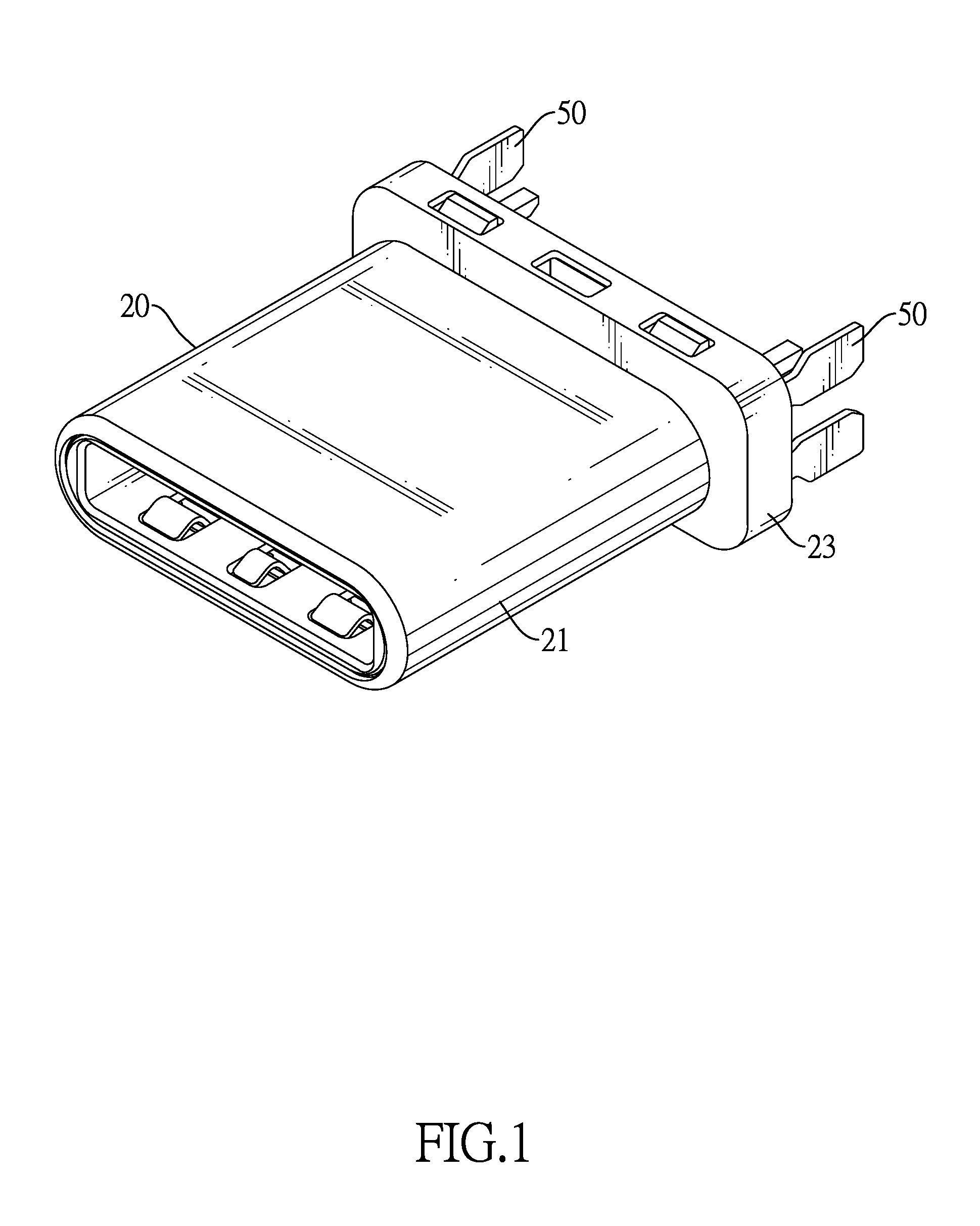
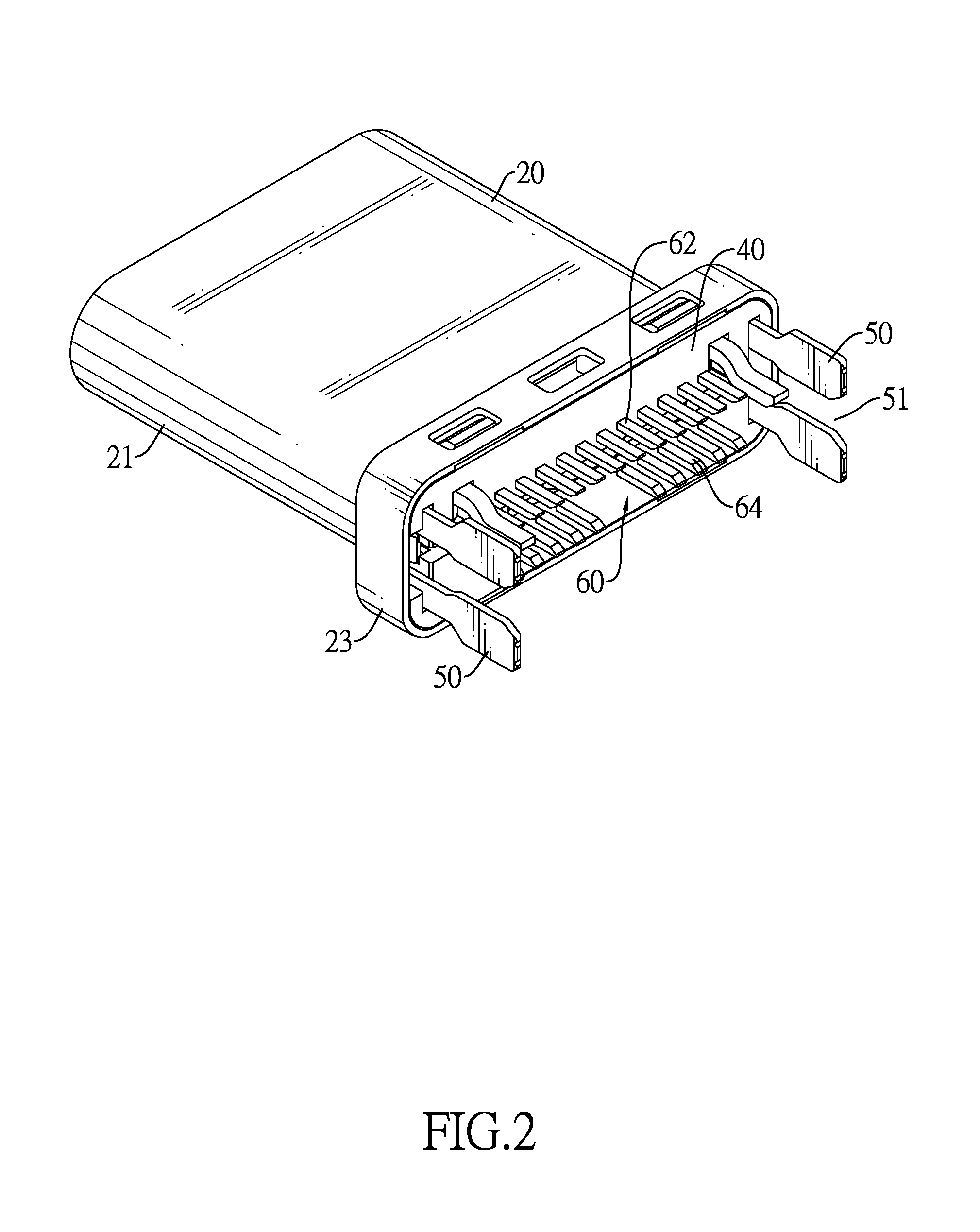
[0030]With reference to FIGS. 1 to 5, a first embodiment of an electrical connector in accordance with the present invention includes a shell 20, an insulating body 30, a base 40, a pair of holding pieces 50, a terminal set 60 and a shielding piece 70.

[0031]The shell 20 is made of metal and the material of the shell 20 may include but is not limited to iron, compound of iron or alloy. The shell 20 is formed by a two-stage drawing process and a punch press process in generation of a front drawing portion 21 and a rear drawing portion 23. The rear drawing portion 23 is ring-shaped and is connected to a rear end of the front drawing portion 21. The front drawing portion 21 and the rear drawing portion 23 may be integrally formed.

[0032]The rear drawing portion 23 is integrally formed and takes th...


PUM


Abstract

An electrical connector has a base, a terminal set, a pair of holding pieces, an insulating body and a shell. The base has two holding piece slots respectively formed in two sides of the bottom of base. The pair of holding pieces is assembled into the holding piece slots respectively. Each holding piece is C-shaped and has a notch formed in a rear end of the holding piece and serving to hold a PCB board. A front end of each holding piece is assembled into the base. Given the pair of holding pieces with an assemblable structure, the size of the holding pieces can be tailored to the requirement of customers. The shell is formed by a two-stage of drawing process to enhance overall strength of the shell to facilitate the plating process afterwards.

Description

BACKGROUND OF THE INVENTION[0001]1. Field of the Invention[0002]The present invention relates to an electrical connector, and more particularly to an electrical connector capable of being assembled with a pair of holding pieces.[0003]2. Description of the Prior Art[0004]Electrical connectors are widely used in electronic devices nowadays. In view of booming 3C smart devices, everyone seems to have possession of one smart device. As such, electrical connectors become an essential and critical electronic element for 3C smart device. Conventional electrical connectors having the USB (Universal Serial Bus) type-C connector are taken as the electrical connectors for the specification of USB 3.0 and other later revisions. What worth mentioning about USB 3.0 is its support of forward and reverse plug for ensuring normal operation regardless of whether a USB type-C plug is plugged in a USB type-C socket forwardly or reversely. Furthermore, USB 3.0 is advantageous in much faster transmission...

Claims


Application Information

Patent Timeline
Patent Type & Authority Patents(United States)
IPC IPC(8): H01R13/64H01R24/64H01R12/72H01R107/00
CPCH01R12/722H01R13/64H01R24/64H01R2107/00H01R13/6593
Inventor KAO, YA-FENTSAI, YU-LUNHOU, PIN-YUANLIAO, CHUNG-FUCHEN, LONG-FEIZHOU, YANG-YANG
Owner ADVANCED CONNECTEK INC
Learn More