Thermal radiation testing device and method
A test device and heat radiation technology, which are applied in the field of heat radiation test, can solve the problem of inability to effectively test the heat preservation and heat insulation ability of radiation type heat preservation and heat insulation thin-layer coatings.
- Summary
- Abstract
- Description
- Claims
- Application Information
AI Technical Summary
Problems solved by technology
Method used
Image

Examples
Embodiment 1
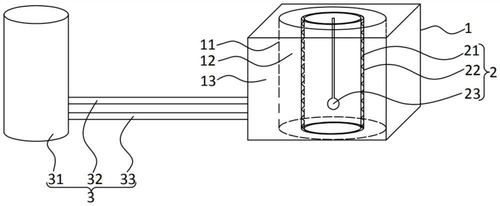
[0034] like figure 1 As shown, the present embodiment provides a thermal radiation testing device for testing the thermal insulation capability of the radiation-type thermal insulation thin-layer coating 21. The thermal radiation testing device includes an incubator 1, a temperature detection device 2 and a heat source. Wherein, the insulated box 1 has a heat transfer cylinder 11 . The temperature detection device 2 is placed in the heat transfer cylinder 11 and can form a vacuum chamber 12 with the heat transfer cylinder 11 . The outer surface of temperature detection device 2 can be coated with radiation type thermal insulation thin-layer paint 21. The heat source is arranged in the incubator 1, and can deliver heat to the temperature detection device 2 through the vacuum chamber 12.
[0035] At present, in the testing of the thermal insulation capacity of thermal insulation materials, it is generally based on heat conduction technology, and the measurement method based o...
Embodiment 2
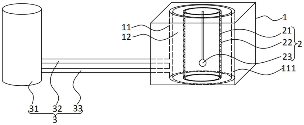
[0050] The thermal radiation detection device provided in this embodiment is substantially the same as the thermal radiation detection device provided in Embodiment 1, such as figure 2 As shown, the main difference between this thermal radiation detection device and the thermal radiation detection device in Embodiment 1 is that: the heat transfer cylinder 11 is a composite structure with an interlayer 111 inside, and the heat source is located in the interlayer 111. Specifically, in this embodiment, the heat source is water. In addition, in this embodiment, the liquid inlet pipe 32 communicates with the heater 31 and the interlayer 111 , and the liquid outlet pipe 33 communicates with the interlayer 111 and the heater 31 .
[0051] The rest of the structure of the thermal radiation detection device provided in this embodiment is the same as that of the thermal radiation detection device in Embodiment 1, and will not be repeated here.
Embodiment 3
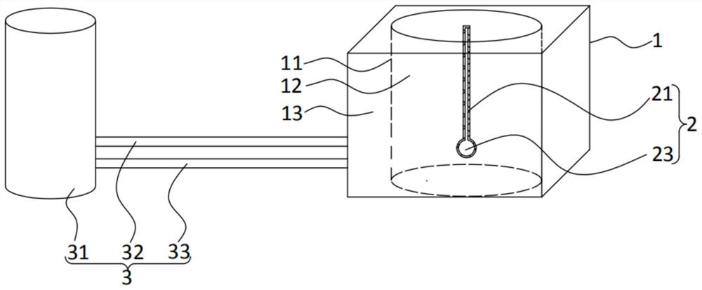
[0053] The thermal radiation detection device provided in this embodiment is substantially the same as the thermal radiation detection device provided in Embodiment 1, such as image 3 As shown, the main difference between the thermal radiation detection device and the thermal radiation detection device in Embodiment 1 is that the temperature detection device 2 is a temperature detector 23, does not include a heat conduction container 22, and is coated with a radiation-type thermal insulation thin-layer coating 21 on the surface of the temperature detector 23.
[0054] The rest of the structure of the thermal radiation detection device provided in this embodiment is the same as that of the thermal radiation detection device in Embodiment 1, and will not be repeated here.
PUM
 Abstract
Description
Claims
Application Information
 - R&D
- Intellectual Property
- Life Sciences
- Materials
- Tech Scout
- Unparalleled Data Quality
- Higher Quality Content
- 60% Fewer Hallucinations
Browse by: Latest US Patents, China's latest patents, Technical Efficacy Thesaurus, Application Domain, Technology Topic, Popular Technical Reports.
© 2025 PatSnap. All rights reserved.Legal|Privacy policy|Modern Slavery Act Transparency Statement|Sitemap|About US| Contact US: help@patsnap.com