Electromagnetic clutch

An electromagnetic clutch and mating technology, applied in the field of clutches, can solve the problems of high cost, large external size, poor heat dissipation, etc., and achieve the effects of low cost, convenient installation and operation, and small volume

Pending Publication Date: 2021-03-30
CHANGZHOU INST OF MECHATRONIC TECH
View PDF0 Cites 0 Cited by
  • Summary
  • Abstract
  • Description
  • Claims
  • Application Information

AI Technical Summary

Problems solved by technology

[0005] In view of this, the present invention aims to propose an electromagnetic clutch, which solves the problems of relatively large external dimensions, relatively high cost and poor heat dissipation of current small torque electromagnetic clutches, and has the advantages of miniaturization, low cost and good heat dissipation

Method used


Image

  • Electromagnetic clutch
  • Electromagnetic clutch
  • Electromagnetic clutch

Examples


Embodiment Construction

[0026] It should be noted that, in the case of no conflict, the embodiments of the present invention and the features in the embodiments can be combined with each other.

[0027] The present invention will be described in detail below with reference to the accompanying drawings and examples.

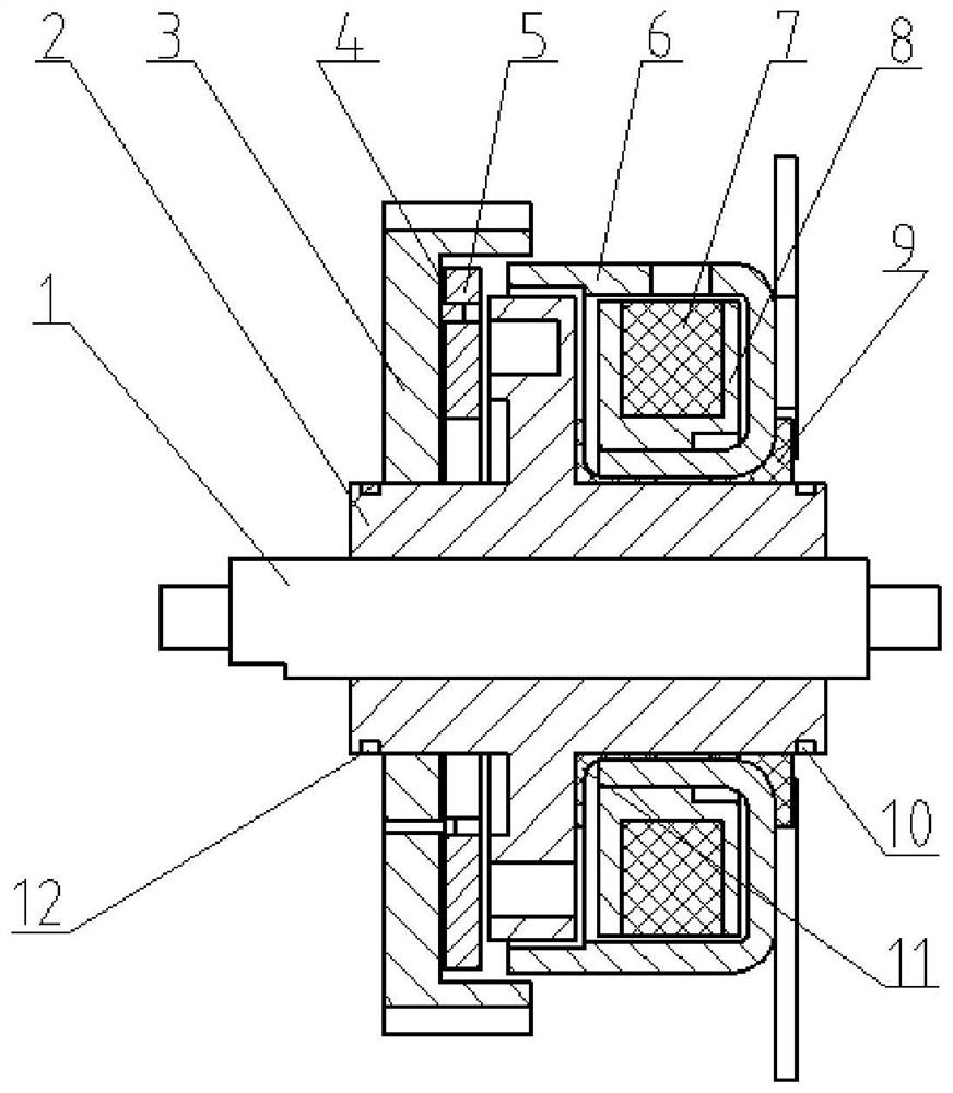
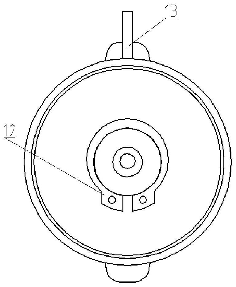
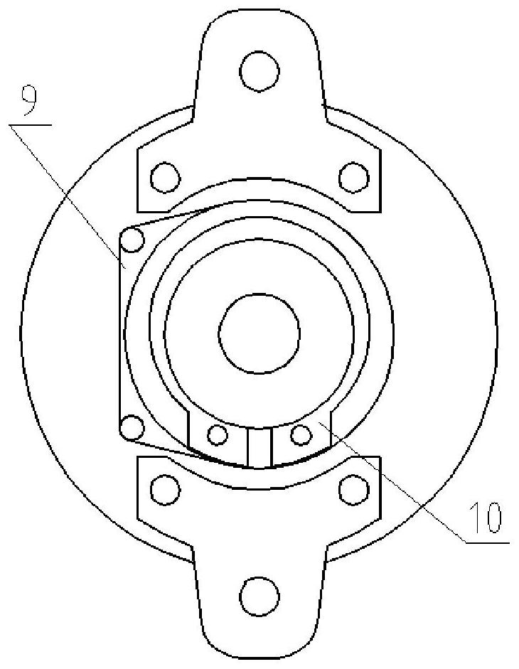
[0028] Such as Figure 1-Figure 6 As shown, an electromagnetic clutch includes a rotating disk 2, an output gear 3, a butterfly spring 4, an armature 5, a housing 6, a coil 7, a first retaining spring 10 and a second retaining spring 12, and the rotating disk 2 includes The hollow shaft 201 and the disc body 202, the disc body 202 is sleeved on the hollow shaft 201, and the disc body 202 and the hollow shaft 201 are integrally formed, and several waists are evenly provided on the upper end surface of the disc body 202 along the circumferential direction. The upper end surface of the disc body 202 is divided into the first friction ring 14 and the second friction ring 15, and an annular ...


PUM


Abstract

The invention provides an electromagnetic clutch. The clutch comprises a rotating disc, an output gear, a belleville spring, an armature, a shell, a coil, a first clamping spring and a second clampingspring, the rotating disc comprises a hollow shaft and a disc body, the disc body is arranged on the hollow shaft in a sleeving manner and integrally formed, and a plurality of kidney-shaped heat dissipation holes are evenly formed in the upper end face of the disc body in the circumferential direction. The upper end face of the disc body is divided into a first friction ring and a second friction ring, an annular heat dissipation groove is formed in the upper end face of the matching position of the disc body and the hollow shaft in the circumferential direction, the upper end of the hollowshaft is matched with the output gear, and the belleville spring is fixedly arranged on the lower end face of the output gear and riveted to the armature. The lower end of the hollow shaft is loaded in the shell, a coil rack is arranged in the shell, the coil is wound in the coil rack, and an outgoing line of the coil penetrates out of the shell to be connected with a power supply. The problems that an existing small-torque electromagnetic clutch is larger in boundary dimension, higher in cost and relatively poor in heat dissipation performance are solved, and the electromagnetic clutch has the advantages of being small in size, low in cost and good in heat dissipation performance.

Description

technical field [0001] The invention belongs to the technical field of clutches, in particular to an electromagnetic clutch. Background technique [0002] Electromagnetic clutch is also called electromagnetic coupling. It uses the principle of electromagnetic induction and the friction between the inner and outer friction plates to make the two rotating parts in the mechanical transmission system, and the driven part can be combined or separated from the electromechanical connection when the active part does not stop rotating. A device is an electrical appliance that performs automatically. [0003] With the rise of domestic smart homes and the continuous development of new energy vehicles such as electric vehicles, the demand and application of various intelligent and miniaturized actuators are becoming more and more extensive. The electromagnetic clutch is transmitted from one side of the shaft to the side of the driven shaft. It is widely used in various transmission me...

Claims


Application Information

Patent Timeline
Patent Type & Authority Applications(China)
IPC IPC(8): F16D27/112F16D27/14
CPCF16D27/112F16D27/14F16D2300/12
Inventor 王峰朱德宁田定康陈慧田宏霞
Owner CHANGZHOU INST OF MECHATRONIC TECH
Why Eureka
Try Eureka