Hydraulic combined punching and shearing machine

A punching and shearing machine, hydraulic technology, applied in the direction of metal processing equipment, stripping devices, manufacturing tools, etc., can solve the problems that V-shaped plates cannot be produced well, and the plate processing process is complicated, so as to facilitate one-time forming and reduce The effect of processing procedure and ease of blanking

Pending Publication Date: 2021-03-30
安徽省重望精密机械制造有限公司
View PDF0 Cites 0 Cited by
  • Summary
  • Abstract
  • Description
  • Claims
  • Application Information

AI Technical Summary

Problems solved by technology

[0003] However, the current production equipment cannot produce V-shaped plates very well. The main reasons are as follows: 1. The processing process of the plates is still as complicated, cutting first and then bending; 2. The inner angle of the plates has various styles besides right angles. With other angles, e.g. a rhombus cross-section for ventilation ducts

Method used


Image

  • Hydraulic combined punching and shearing machine
  • Hydraulic combined punching and shearing machine
  • Hydraulic combined punching and shearing machine

Examples


Embodiment 1

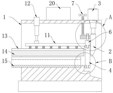
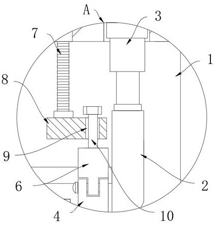
[0031] refer to Figure 1-7 , a hydraulic combined punching and shearing machine, comprising a punching and shearing body 1, the punching and shearing body 1 is a box-type structure with left and right openings, a punching and shearing tool 2 is installed at the inner right end of the punching and shearing body 1, and the punching and shearing tool 2 adopts a first hydraulic rod 3 to drive up and down displacement, and the punching and shearing lower die with adjustable angle is also arranged inside the punching and shearing machine body 1.

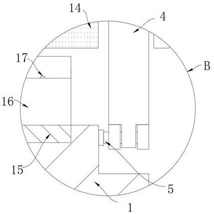
[0032] The right side of the punching and shearing die is attached to the left side of the punching and shearing tool 2. The punching and shearing die is composed of two corner dies 4, and the bottom ends of the two corner dies 4 are provided with through holes and pass through The positioning shaft 5 is rotatably connected to the right end of the inner bottom wall of the punching and shearing body 1, and the tops of the two corner dies 4...

Embodiment 2

[0039] refer to Figure 8-12 , Different from Embodiment 1, the right end inner top wall of the punching and shearing machine body 1 and the right side of the punching and shearing tool 2 are respectively equipped with the sensing end and the moving end of the contact switch 21, and the contact switch 21 is coupled with the controller 20.

[0040] The right end of the punching and shearing machine body 1 is equipped with a size adjustment assembly composed of a positioning frame 22, an adjustment screw 23, a wheel disc 24 and a moving plate 25, and the moving plate 25 is sleeved on the surface of the adjustment screw 23 through an internally threaded sleeve 26. Two guide rods 27 are also arranged inside the positioning frame 22 .

[0041] The bottom end of the moving plate 25 is equipped with an air control box 28, the upper surface of the air control box 28 is fixedly connected with an air intake pipe 29, the air intake pipe 29 communicates with the inner left end of the air ...


PUM


Abstract

The invention discloses a hydraulic combined punching and shearing machine. The hydraulic combined punching and shearing machine comprises a punching and shearing machine body, the punching and shearing machine body is of a box type structure with left and right openings, a punching and shearing tool is installed at the right end of the interior of the punching and shearing machine body, the punching and shearing tool is driven by a first hydraulic rod to move up and down, and a punching and shearing lower die with an adjustable angle is further arranged in the interior of the punching and shearing machine body. According to the hydraulic combined punching and shearing machine, by arranging a forming lower die and a forming upper die, a common plate can be conveniently punched into a V-shaped structure in the punching and shearing process, then punching and shearing cutting is conducted through cooperation of the punching and shearing lower die composed of corner dies and the punchingand shearing tool to achieve a target length, so that one-time forming is facilitated, machining procedures are greatly reduced, and the production efficiency is improved; meanwhile, the included angle between the two corner dies can be adjusted, and the lower forming die and the upper forming die are convenient to replace; the included angle is adjusted, and the upper forming die and the lower forming die which are matched with each other are replaced when V-shaped plates with other angles are machined, so that the hydraulic combined punching and shearing machine is applicable to machining the V-shaped plates with the different angles.

Description

technical field [0001] The invention relates to the technical field of mechanical equipment, in particular to a hydraulic combined punching and shearing machine. Background technique [0002] Most of the ventilation ducts in the underground garage or basement have a rectangular, rhombus or circular cross-section for ventilation and heat dissipation or for conveying cold air. In the process of processing, the thinner metal sheet is first bent. During the bending process, it is bent three times, and then welded and assembled to form a pipe body. In order to simplify the forming of the pipeline, an existing one is shown in the accompanying drawings Figure 6-7 As shown in the ventilation duct and its cross-sectional display, the duct is formed by splicing two V-shaped plates, which greatly simplifies the processing process and improves production efficiency. [0003] However, the current production equipment cannot produce V-shaped plates very well. The main reasons are as fol...

Claims


Application Information

Patent Timeline
IPC IPC(8): B21D28/02B21D28/14B21D45/06B21D37/04
CPCB21D28/02B21D28/14B21D45/06B21D37/04
Inventor 夏华洲
Owner 安徽省重望精密机械制造有限公司
Why Eureka
Try Eureka