
Coal economizer bypass flue outlet high-temperature and low-temperature flue gas flow mixing device

A technology of bypass flue and economizer, applied in the field of flue gas denitrification, can solve the problems of flue gas temperature field variation at catalyst inlet, denitrification efficiency reduction, catalyst activity decline, etc.

Pending Publication Date: 2021-03-30
SUZHOU XIRE ENERGY SAVING ENVIRONMENTAL PROTECTION TECH CO LTD +1
View PDF2 Cites 0 Cited by
  • Summary
  • Abstract
  • Description
  • Claims
  • Application Information

AI Technical Summary

Problems solved by technology

[0007] In order to solve the problem that the flue gas temperature field at the catalyst inlet of the coal-fired power plant becomes worse after the bypass flue of the economizer is put into operation at medium and low loads in the existing technology, which leads to a decrease in catalyst activity in the low temperature area, a decrease in denitrification efficiency, an increase in ammonia slip rate and The problem of ABS, the purpose of the present invention is to provide a high and low temperature flue gas mixing device at the outlet of the economizer bypass flue

Method used


Image

  • Coal economizer bypass flue outlet high-temperature and low-temperature flue gas flow mixing device
  • Coal economizer bypass flue outlet high-temperature and low-temperature flue gas flow mixing device
  • Coal economizer bypass flue outlet high-temperature and low-temperature flue gas flow mixing device

Examples


Embodiment 1

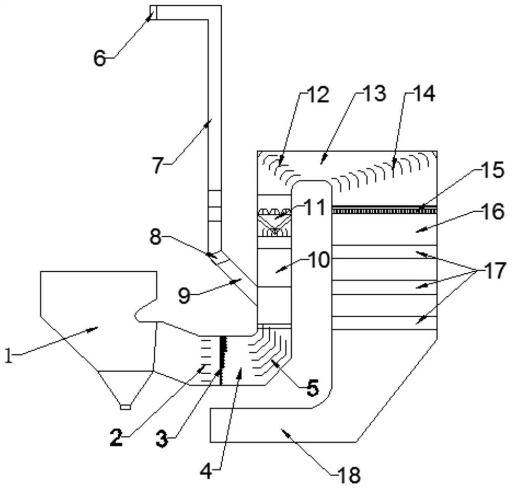
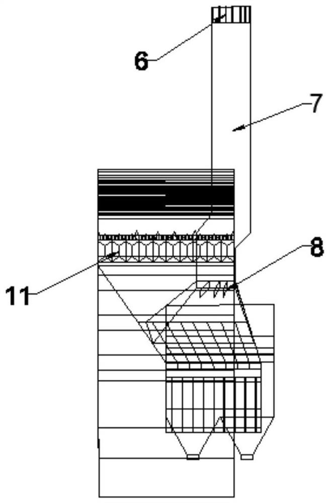
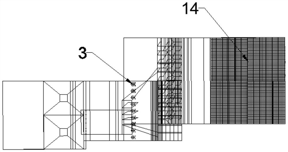
[0031] Such as Figure 1-6 and Figure 8 As shown, a high and low temperature flue gas mixing device at the outlet of the bypass flue of the economizer has two groups, which are the high and low temperature flue gas mixing device A at the outlet of the bypass flue of the economizer and the high temperature flue gas at the outlet of the bypass flue of the economizer. The low-temperature flue gas mixing device B, both of which are connected to the boiler in front and arranged symmetrically around the boiler, taking one of the high-low temperature flue gas mixing devices at the outlet of the economizer bypass flue as an example, the structure is described as follows:

[0032]Each group of economizer bypass flue outlet high and low temperature flue gas mixed flow device includes economizer bypass flue and SCR denitrification device connected, including: economizer outlet flue 1, main baffle door 2 , SCR ammonia injection system 3, SCR denitrification device inlet horizontal flue ...


PUM


Abstract

The invention discloses a coal economizer bypass flue outlet high-temperature and low-temperature flue gas flow mixing device, which is characterized in that a coal economizer is communicated with anSCR denitration reactor sequentially through a coal economizer outlet flue, an SCR denitration device inlet horizontal flue, an SCR denitration device ascending flue, a large-scale flue gas mixer andan SCR top horizontal flue; and an ascending flue of the SCR denitration device is communicated with a bypass flue of the coal economizer and then is communicated to the boiler. According to the coaleconomizer bypass flue outlet high and low temperature flue gas flow mixing device, coal economizer outlet low temperature flue gas and boiler low temperature superheater inlet high temperature flue gas are mixed through the large-scale flue gas mixer and then enter the SCR denitration reactor through a SCR top horizontal flue; large-range mixing of high-temperature flue gas and low-temperature flue gas on the two sides in the whole depth direction of a flue can be achieved, the temperature distribution uniformity of flue gas at an inlet of an SCR catalyst layer reaches the optimal level, theproblem of flue gas temperature mixing after a low-load economizer bypass is put into operation is solved, and the application prospect is wide.

Description

technical field [0001] The invention belongs to the technical field of flue gas denitrification, and in particular relates to a high and low temperature flue gas mixing device at the outlet of a bypass flue of an economizer. Background technique [0002] SCR: Selective Catalytic Reduction, referred to as SCR. SCR denitrification technology refers to the reduction agent (such as liquid ammonia, urea and ammonia water, etc.) in the range of 310 ~ 420 ° C, under the action of a catalyst, "selectively" react with NOx in the flue gas to generate pollution-free N 2 and H 2 O's NOx emission reduction technology. [0003] At present, it has become an inevitable trend for thermal power plants to participate in flexible peak shaving. The primary goal is to reduce the minimum technical output of the unit, so that the thermal power unit can increase the peak shaving capacity by 20% of the rated capacity, and the minimum technical output reaches 40-50% of the rated capacity. The minim...

Claims


Application Information

Patent Timeline
IPC IPC(8): B01D53/90B01D53/56F23J15/02F23J15/06
CPCB01D53/8631B01D53/90B01D2251/2062B01D2255/902B01D2258/0283F23J15/022F23J15/06
Inventor 韦振祖王建阳黄见勋何金亮谢新华李明磊卢承政黄飞周健张庚
Owner SUZHOU XIRE ENERGY SAVING ENVIRONMENTAL PROTECTION TECH CO LTD
Learn More