Heat dissipation assembly, device needing heat dissipation and preparation method of heat dissipation assembly
A technology for heat dissipation components and components, which is applied in semiconductor/solid-state device manufacturing, electrical components, electric solid-state devices, etc., and can solve problems such as the structure is easily destroyed, the strength of graphite sheets is low, and the effect is reduced.
- Summary
- Abstract
- Description
- Claims
- Application Information
AI Technical Summary
Problems solved by technology
Method used
Image


Examples
Embodiment 1
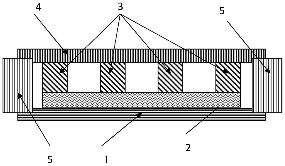
[0108] Such as figure 2 As shown in (b), the heat dissipation assembly of Embodiment 1 includes an evaporating element, a liquid absorbing element 2, a cooling element and a sealing element. The liquid-absorbing element 2 is a 500-mesh stainless steel mesh (area: 60*60*0.05mm 3 , Wire diameter: 25 microns, mesh size: 25 microns). The stainless steel mesh was first activated at a current of 2 A for 2 minutes, and then, the stainless steel mesh was washed with deionized water and washed with 0.8M CuSO 4 and 1.5M H 2 SO 4 Electroplate at a current of 1 A for 5 min in the fixative solution. In this way, a micron-sized stainless steel mesh coated with a copper layer is obtained as a liquid-absorbing element. Figure 7 a shows a SEM image of a stainless steel mesh coated with copper.
[0109] The cooling and evaporating elements are 40 μm and 30 μm thick copper plates, respectively. An array of microcopper pillars is designed on a copper plate as a cooling element to support...
Embodiment 2
[0111] Such as figure 2 As shown in (c), the heat dissipation assembly of Example 2 was prepared in substantially the same manner as in Example 1, except that a flower-like nanostructure was formed on a copper-plated stainless steel mesh. Specifically, a copper-plated stainless steel mesh was immersed in a solution containing 0.065M K 2 S 2 o 8 and 2.5M KOH in 70°C aqueous solution for 30 minutes. The samples were rinsed with water and dried at 180°C for 1 hour. results, such as Figure 7 As shown in b and c, at least a part of the surface of the stainless steel mesh is covered by flower-like nanostructures. The surface with flower-like nanostructures has a contact angle with water of less than 10 degrees. Therefore, the nanostructured mesh surface is superhydrophilic, which can greatly enhance the capillary force. The thickness of the heat dissipation component in Example 2 is 230 microns.
Embodiment 3
[0113] Such as figure 2 As shown in (d), the heat dissipation assembly of Example 2 was prepared in substantially the same manner as in Example 2, except that a wetting surface with a hydrophilic network of hydrophobic island arrays was also formed on the inner surface of the copper plate of the evaporation element. Specifically, at 70*70*0.03mm 3 To manufacture hydrophobic islands on the surface of a copper substrate, firstly, a HPR504 photoresist pattern is formed on a clean copper substrate by photolithography to protect the hydrophilic area. The samples were then immersed in a solution containing FAS (fluoroalkylsilane) to form hydrophobic islands. Finally the photoresist was removed, resulting in an array of square hydrophobic islands of 45 μm in size with a pitch of 65 μm on the hydrophobic surface. Figure 6 (a) shows a photograph of the fabricated square hydrophobic island array, and Figure 6 (b) shows condensation of vapor on the hydrophobic area, demonstrating t...
PUM
 Abstract
Description
Claims
Application Information
 - Generate Ideas
- Intellectual Property
- Life Sciences
- Materials
- Tech Scout
- Unparalleled Data Quality
- Higher Quality Content
- 60% Fewer Hallucinations
Browse by: Latest US Patents, China's latest patents, Technical Efficacy Thesaurus, Application Domain, Technology Topic, Popular Technical Reports.
© 2025 PatSnap. All rights reserved.Legal|Privacy policy|Modern Slavery Act Transparency Statement|Sitemap|About US| Contact US: help@patsnap.com